Note:Ensurethisisdoneforeachlever.
5.Movethemotion-controlleversinwardtotheneutral
positionandturntheignitionkeytotheRunposition.
Note:Donotstartthemachine.
Note:Themachineisnowabletobepushedbyhand.
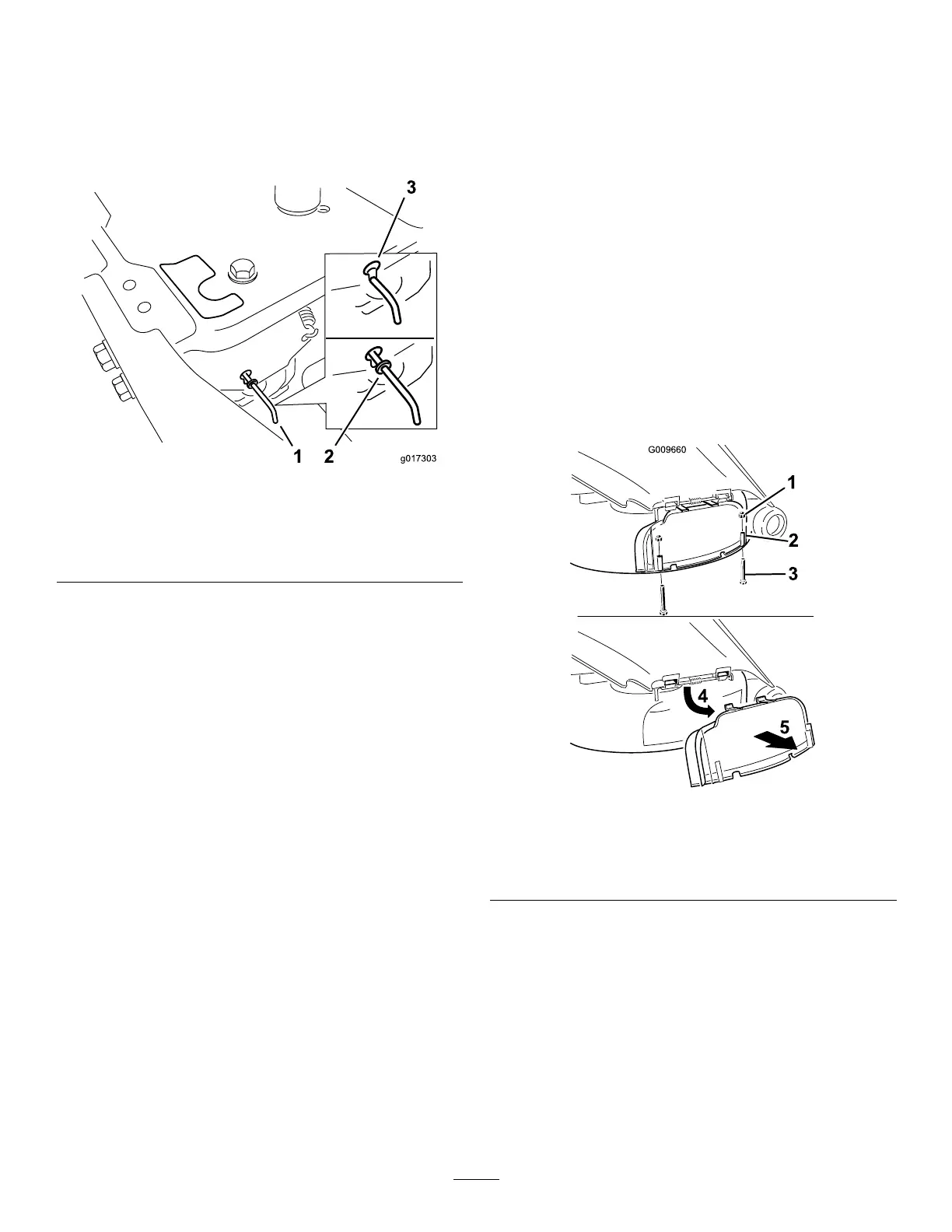
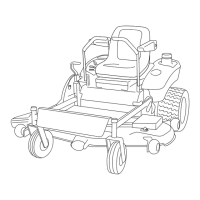
Figure24
1.Bypass-leverlocations
3.Leverpositionforpushing
themachine
2.Leverpositionfor
operatingthemachine
6.Whennished,ensurethatthekeyhasbeenreturnedto
theStoppositiontoavoiddrainingthebatterycharge.
Note:Ifthemachinefailstomove,theelectricbrakemay
stillbeengaged.Ifnecessary,theelectricbrakecanbereleased
manually;refertoReleasingtheElectricBrake(page41).
OperatingtheMachine
Movethebypassleversrearwardthroughthekeyholeand
downtolocktheminplaceasshowninFigure24.
Note:Ensurethisisdoneforeachlever.
ConvertingtoSideDischarge
(formodelswith107cm
(42-inch)decks)
Themowerdeckandmowerbladesshippedwiththismachine
weredesignedforoptimummulchingandsidedischarge
performance.
RemovingtheDischargeCoverforthe
SideDischarge
1.Parkthemachineonalevelsurfaceanddisengagethe
blade-controlswitch.
2.Movethemotion-controlleversoutwardtopark
position,stoptheengine,removethekey,andwaitfor
allmovingpartstostopbeforeleavingtheoperating
position.
3.Removethe2boltsandnutsthatsecurethedischarge
covertothemower(Figure25).
Figure25
1.Capnut(1/4inch)
4.Rotatethecoverup
2.Dischargecover5.Removethecover
3.Bolt(1/4x2-1/2inches)
4.Removethedischargecover.
5.Liftupthegrassdeector,andlocatethelocknuton
thedeectorpivotrod.
6.Removetheexistingthinnut(3/8inch).
7.Installthecutoffbafetotheexposedpivotrod
(Figure26).
Note:Usetheexistingthinnut(3/8inch)tosecure
thebafetothemower.
Note:Thecutoffbafewasshippedwiththemachine
asaloosepart.
26