5
Installing the Attachment
Mount
Parts needed for this procedure:
1
Stabilizer bracket
2
Carriage bolt (5/16 x 3/4 inch)
4
Locknut (5/16 inch)
2
Self-tapping screw (5/16 x 3/4 inch)
2
Bolt (5/16 x 1 inch)
1
Pivot frame
2 Hairpin cotter
2 Rod
2 W asher
Installing the Stabilizer Bracket
and Pivot Frame
1. Install the stabilizer bracket to the engine guard
using 2 carriage bolts (5/16 x 3/4 inch) and 2
locknuts (5/16 inch) ( Figure 7 ).
g300204
Figure 7
1. Carriage bolt (5/16 x 3/4
inch)
2. Locknut (5/16 inch)
2. Install the pivot frame to the machine frame as
shown in Figure 8 . Secure the pivot frame to the
machine frame using 2 bolts (5/16 x 1 inch) and
2 locknuts (5/16 inch).
Note: Remove the hitch bracket and hardware
if they are installed.
g300205
Figure 8
1. Locknut (5/16 inch) 2. Bolt (5/16 x 1 inch)
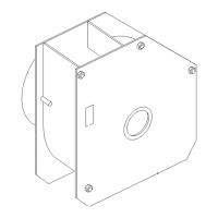
3. Secure the pivot frame to the bottom of the
machine frame using 2 self-tapping screws (5/16
x 3/4 inch) as shown in Figure 9 .
g300206
Figure 9
1. Self-tapping screw (5/16 x 3/4 inch)
4. Install the bent, ared end of a rod into the keyed
slot in the left side of the machine frame, and
move the rod rearward to seat it in the frame
( Figure 10 ).
Note: Repeat this step for the right side of the
machine.
8