5. Hook the exible latch on the chute to the
retaining clasp welded on the mower deck.
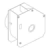
g299268
Figure 40
1. Chute
3. Flexible latch
2. Retaining clasp
W ARNING
W ithout the grass deector , bagger tubes or
complete bagger assembly mounted in place,
you and others are exposed to blade contact
and thrown debris. Contact with the rotating
mower blade(s) and thrown debris will cause
injury or death.
• Always install the grass deector when
removing the bagger and changing to side
discharge mode.
• If the grass deector is ever damaged,
replace it immediately . The grass deector
routes material down toward the turf.
• Never put your hands or feet under the
mower .
• Never try to clear the discharge area or
mower blades unless you move the power
take off (PT O) to off and rotate the ignition
key to off. Also remove the key and pull
the wire off of the spark plug(s).
• T urn off the engine before unclogging the
discharge chute.
1 1
Connecting with the
Discharge T ube
No Parts Required
Procedure
1. Slide the curved end of the discharge tube into
the opening in the bagger top ( Figure 41 ).
g33971 1
Figure 41
1. Discharge tube, curved
end
4. Peg
2. Opening in bagger top
5. Rubber strap
3. Discharge tube, ared end
2. Slide the ared end of the discharge tube over
the end of the chute. Move the rubber retaining
strap on the chute snaps over the peg on the
discharge tube to secure it ( Figure 41 ).
3. After the bagger installation, install the wire onto
the spark plug(s).
19