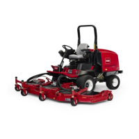
Figure81
1.Height-of-cutchain
2.U-bolt
AdjustingtheWingCuttingUnits
1.Removethecapscrewsandnutssecuringthecastor
armtothecastorfork(Figure82).
2.Repositiontheshims,asrequired,toraiseorlower
thecastorwheeluntilthecuttingunithasthecorrect
pitch.
3.Installthecapscrewsandnuts.
Figure82
1.Castorwheel4.Shims
2.Tensioningcap5.Axlemountingholes
3.Spacers
ServicingtheCastorArm
Bushings
Thecastorarmshavebushingspressedintothetopand
bottomofthetubeandaftermanyhoursofoperation,
thebushingswillwear.Tocheckthebushings,movethe
castorforkbackandforthandfromsidetoside.Ifthe
castorspindleislooseinsidethebushings,thebushings
arewornandmustbereplaced.
1.Raisethecuttingunitsothatthewheelsareoffof
theoor.Blockthecuttingunitsothatitcannot
accidentallyfall.
2.Removethetensioningcap,spacer(s),andthrust
washerfromthetopofthecastorspindle.
3.Pullthecastorspindleoutofthemountingtube.
Allowthethrustwasherandspacer(s)toremainon
thebottomofthespindle.
4.Insertapinpunchintothetoporbottomofthe
mountingtubeanddrivethebushingoutofthetube
(Figure83).Alsodrivetheotherbushingoutofthe
tube.Cleantheinsideofthetubestoremovedirt.
Figure83
1.Castorarmtube
2.Bushings
5.Applygreasetotheinsideandoutsideofthenew
bushings.Usingahammerandatplate,drivethe
bushingsintothemountingtube.
6.Inspectthecastorspindleforwearandreplaceitif
itisdamaged.
7.Pushthecastorspindlethroughthebushingsand
mountingtube.Slidethethrustwasherandspacer(s)
ontothespindle.Installthetensioningcaponthe
castorspindletoretainallpartsinplace.
ServicingtheCastorWheels
andBearings
ServiceInterval:Every800hours
1.Removethelocknutfromtheboltholdingthecastor
wheelassemblybetweenthecastorfork(Figure84)
orthecastorpivotarm(Figure85).Graspthecastor
wheelandslidetheboltoutoftheforkorpivotarm.
53

 Loading...


