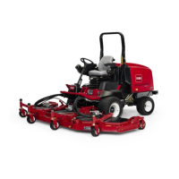
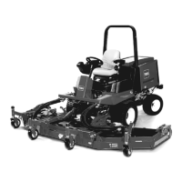
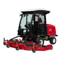
Figure84
1.Castorwheel
3.Bearing
2.Castorfork
4.Bearingspacer
Figure85
1.Castorwheel
3.Bearing
2.Castorpivotarm
4.Bearingspacer
2.Removethebearingfromthewheelhuband
allowthebearingspacertofallout(Figure84and
Figure85).Removethebearingfromtheopposite
sideofthewheelhub.
3.Checkthebearings,spacer,andinsideofthewheel
hubforwear.Replaceanydamagedparts.
4.Toassemblethecastorwheel,pushthebearinginto
thewheelhub.Wheninstallingthebearings,press
ontheouterraceofthebearing.
5.Slidethebearingspacerintothewheelhub.Pushthe
otherbearingintotheopenendofthewheelhubto
captivatethebearingspacerinsidethewheelhub.
6.Installthecastorwheelassemblybetweenthecastor
forkandsecureitinplacewiththeboltandlocknut.
ReplacingtheCuttingUnit
HingeCovers
Thehingecoverpreventsdebrisfromescapingathinge
pointsbetweencuttingunits.Ifcover(s)everbecome
damagedorwormtheymustbereplaced.
Figure86
1.Hingecover
TighteningtheLocknuts
ServiceInterval:Aftertherst50hours
Aftertherst50hours,thelocknutsonthelowerpivot
links(Figure87),theliftarmpins(Figure88)andthe
wingdeckcylindermounts(Figure89)mustbetorqued
to160to180ft-lb(216to244N⋅m).
Figure87
1.Lowerpivotlinknut(4)
54

 Loading...


