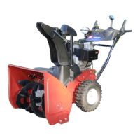
1.5 mm) from the front of the slot to the front edg e of the
pin ( Figure 37 ).
Figure 37
1. Pin
If the left hand (traction) cable is not properly adjusted,
do the follo wing ste ps:
1. Loosen the jam n ut.
2. Loosen or tighten the tur nbuc kle to adjust the pin until
it is the proper g ap from the front edg e of the slot.
3. Tighten the jam n ut ( Figure 38 ).
Figure 38
1. Jam nut
2. Turnbuckle
Checking and Adjusting the
Auger/Impeller Cable
Chec k and adjust the aug er/impeller cable after the first
2 operating hours , then yearly thereafter .
1. R emo v e the 2 screws from the right side of the belt
co v er as sho wn.
2. Lift up the right side of the belt co v er ( Figure 39 ).
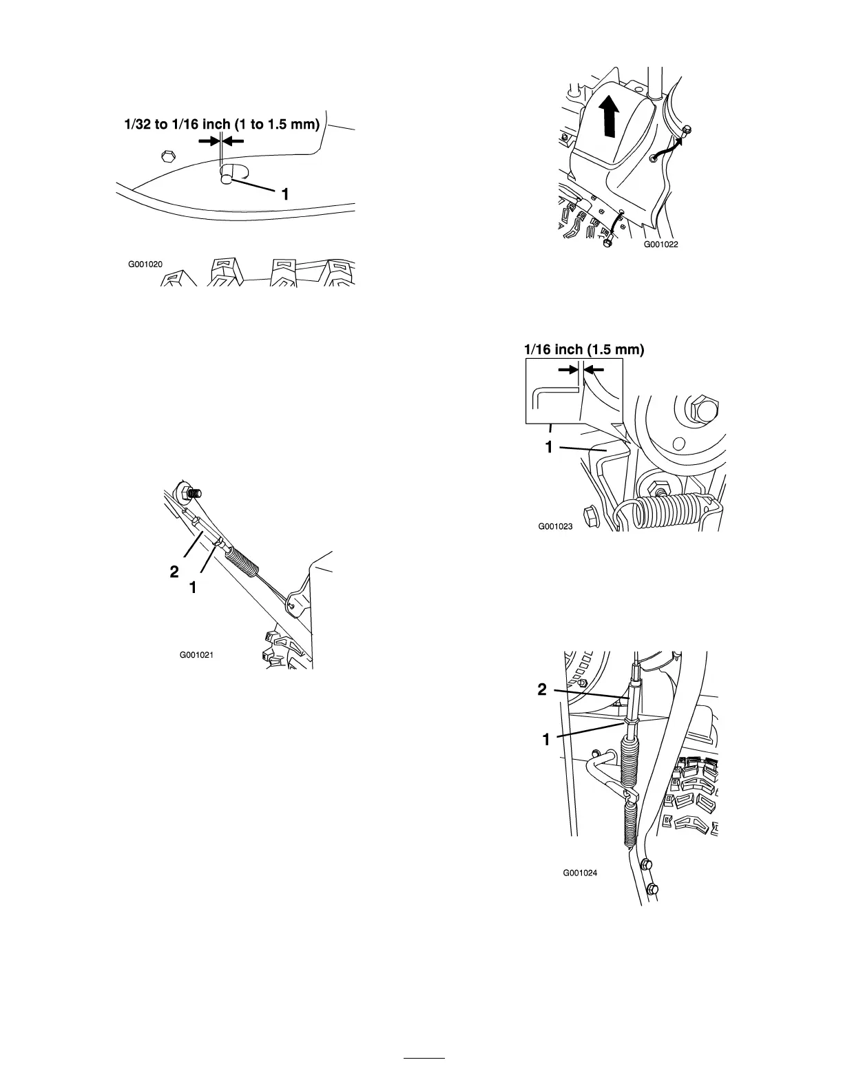
Figure 39
3. With the aug er/impeller lev er diseng ag ed, ensure that
the g ap betw een the aug er clutc h assembly and the tab
is 1/16 inc h (1.5 mm) ( Figure 40 ).
Figure 40
1. Tab
4. If the aug er/impeller cable is not properly adjusted, do
the follo wing ste ps:
5. Loosen the jam n ut ( Figure 41 ).
Figure 41
1. Jam nut
2. Turnbuckle
6. Loosen or tighten the tur nbuc kle that adjusts the
tension on the cable ( Figure 41 ).
7. Adjust the tur nbuc kle until y ou obtain the proper g ap .
16
 Loading...