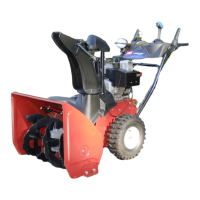
1. Installing the Upper Handle
Note: Do not remo v e the r ubber band until y ou ha v e
installed the upper handle .
1. Lift and rotate the upper handle and position it o v er
the lo w er handle ( Figure 3 ).
Important: R oute the ca bles attached to the
Quick Stick inside the upper handle legs and
ensur e that the ca bles and the wir e f or the headlight
ar e not pinched betw een the handle sections.
Figure 3
1. Cables
2. Secure the upper handle with 4 handle bolts , 4 cur v ed
w ashers , and 4 loc kn uts from the loose par ts bag ( Figure
4 ).
Figure 4
2. Installing the Traction
Control Linkage
1. R emo v e the hair pin cotter and w asher from the lo w er
end of the speed control rod and inser t the lo w er end
of the rod into the lo w er link ar m so that the bent end
of the speed control rod faces rearw ard ( Figure 5 ).
Figure 5
2. Secure the lo w er end of the speed control rod with the
w asher and hair pin cotter that y ou previously remo v ed.
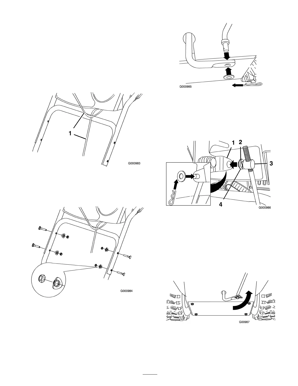
3. R emo v e the hair pin cotter and the outer w asher from
the tr unnion on the upper end of the speed control
rod ( Figure 6 ).
Figure 6
1. Speed selector lever
3. Trunnion
2. Wave washer 4. Flat washer
Note: T o mak e installation easier , lea v e the w a v e
w asher and the flat w asher on the tr unnion ( Figure 6 ).
4. Shift the speed selector lev er into P osition R2.
5. R otate the lo w er link ar m fully upw ard
(countercloc kwise) ( Figure 7 ).
Figure 7
6. Lift up on the speed control rod and inser t the tr unnion
into the hole in the speed selector lev er ( Figure 6 ).
6
 Loading...