Primer Pump Reassembly (cont’d)
a. Gasket
“B”
has two sizes of fuel orifices
one large and one small.
Gasket
“A”
has one size of fuel orifices
both large.
b. Valve seat
“A”
has a locating notch that is
cut through the seat.
Valve seat
“B”
has a locating notch that is
partially cut into the seat.
c. Gasket
“A”
and valve seat
“A”
are inside
the pump. Gasket
“B”
and valve seat
“B”
are to the outside.
2.
Reassemble parts into the pump body. Posi-
tion gasket
B
so
the small fuel orifice is
toward the outlet nozzle of the pump body.
3. Place valve seat
A
with valve seats up, on
gasket
B.
4.
Push one valve cushion into valve seat
A
so
it
covers the double holed fuel orifice.
5.
Place gasket
A
on valve seat
A.
6.
Drop the two ball valves through gasket
A
to
seat in valve seat
A.
7.
Place one valve cushion into valve seat
B
so
8.
Set valve seat
8
with valve cushion into the
9.
Secure all parts by screwing the rubber
10. Reinstall the pump into the tank opening and
that it covers the double-holed fuel orifice.
pump body with assembled parts.
cap/button on the pump body.
attach the fuel line.
Fuel Pickup Tube and Filter Service
1. The fuel filter on the pickup tube can be
inspected without removing the pickup
assembly by “fishing” the filter out through
the filter hole. See Fig. 43.
Figure 43
2.
Pull the pickup weight from the end of the
tube and remove the fiber filter element.
Inspect the element and the fuel strainer
located inside the pickup weight. Clean or
replace as necessary.
3. Reassemble the pickup assembly making
sure that the pickup tube fits snugly on the
top of the fiber filter element.
4.
If pickup tube removal is desired, it can be
removed by removing the primer pump as
described under step of Primer Pump
Disassembly.
5.
Remove the fuel pickup tube by pulling it out
of the tank. It is also pressed in.
6.
Inspect the pickup tube for cracks or
punctures and replace
if
necessary.
7.
Reinstall the fuel pickup tube by lightly
coating the barbed end with two cycle oil and
pressing it into the proper tank orifice.
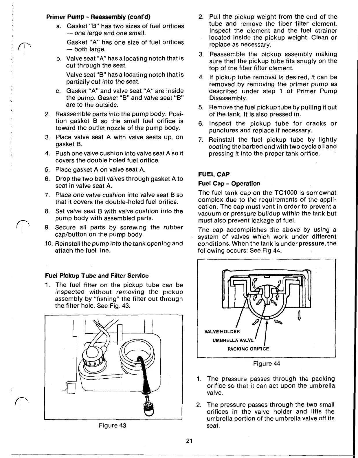
FUEL CAP
Fuel Cap Operation
The fuel tank cap on the TC1000 is somewhat
complex due to the requirements of the appli-
cation. The cap must vent in order to prevent a
vacuum or pressure buildup within the tank but
must also prevent leakage of fuel.
The cap accomplishes the above by using a
system of valves which work under different
conditions, When the tank is under
pressure,
the
following occurs: See Fig
44.
VALVE
HOLDER
UMBRELLA
VALVE
PACKING
ORIFICE
Figure 44
1. The pressure passes through the packing
orifice
so
that it can act upon the umbrella
valve
2.
The pressure passes through the two small
orifices in the valve holder and lifts the
umbrella portion of the umbrella valve
Off
its
seat.
21
 Loading...