SECTION
12
Drive Tube Removal
1.
Remove the engine as described under
Engine Removal from Drive Tube,
page
34.
2.
Remove the control as described under
Control and Grip Removal from Drive Tube,
page
40.
3.
Remove the handle as described under
Handle Removal from Drive Tube,
page
41.
4.
Remove the machine screw and nylon lock-
nut that secures the bearing housing to the
drive shaft. See Fig.
108.
DRIVE TUBE
Figure
108
5.
Pull the bearing housing, shield and trimmer
implement off the drive tube as an assembly.
Drive Tube Service
1.
Insert a
5/8"
diameter hose into the curved
end of the shaft and push the nylon liner out
the top of the tube.
2.
Inspect the nylon sleeve for wear and replace
if
necessary.
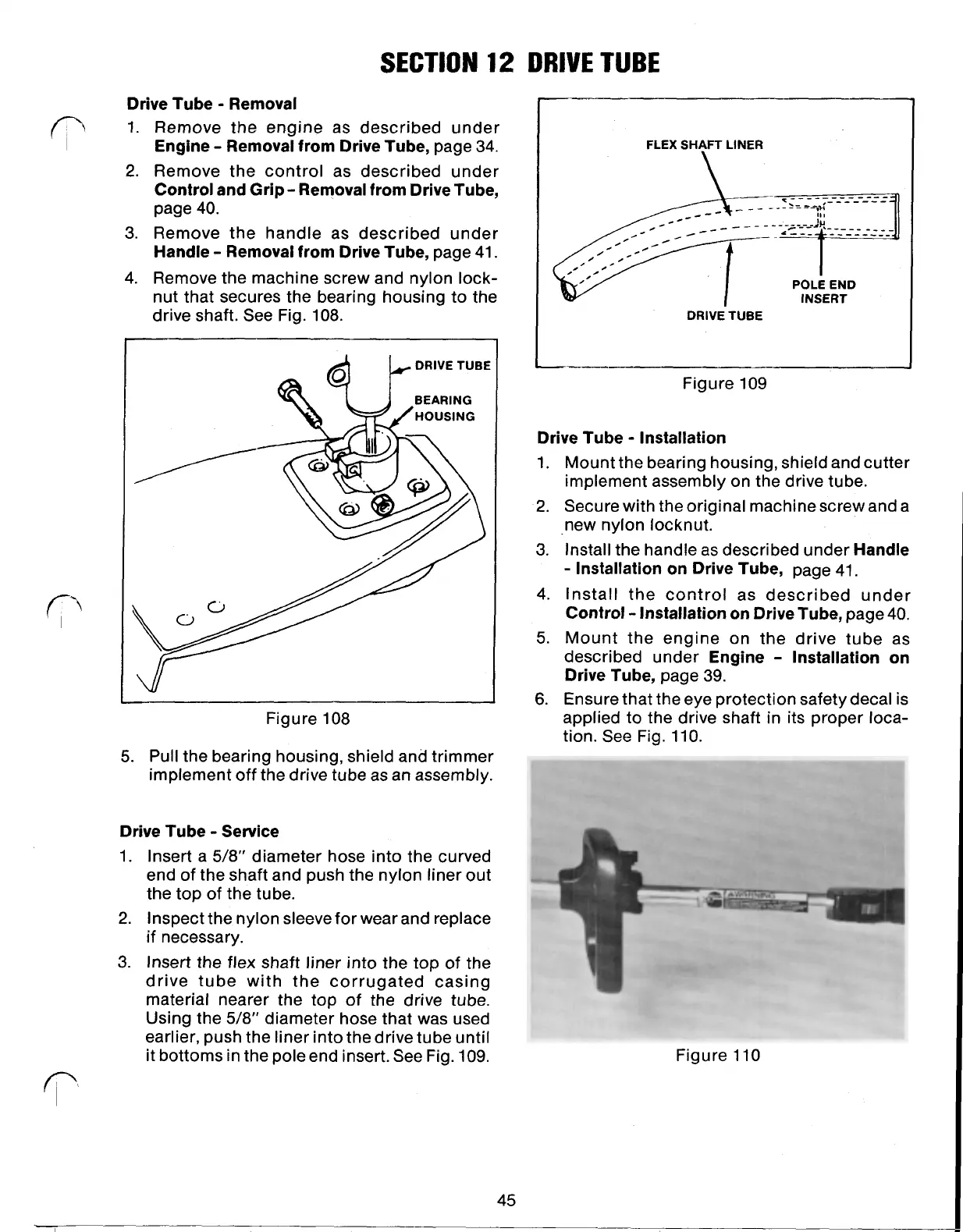
3.
Insert the flex shaft liner into the top of the
drive tube with the corrugated casing
material nearer the top of the drive tube.
Using the
5/8"
diameter hose that was used
earlier, push the liner into the drive tube until
it bottoms in the pole end insert. See Fig.
109.
45
DRIVE
TUBE
FLEX
SHAFT
LINER
POLE END
INSERT
DRIVE TUBE
-~--
Figure
109
Drive Tube Installation
1.
Mount the bearing housing, shield and cutter
implement assembly on the drive tube.
2.
Secure with the original machine screw and a
new nylon locknut.
3.
Install the handle as described under
Handle
Installation on Drive Tube,
page
41.
4.
Install the control as described under
Control Installation on Drive Tube,
page
40.
5.
Mount the engine on the drive tube as
described under
Engine Installation on
Drive Tube,
page
39.
6.
Ensure that the eye protection safety decal is
applied to the drive shaft in its proper loca-
tion. See Fig.
l
10.
Figure
110
 Loading...