Air Gap Adjustment (cont’d)
Air Gap Adjustment
NOTE:
If
coil performance is suspect, check the
air gap with a feeler gauge prior to loosening the
two coil mounting screws. It should be 0.4 to
0.5
mm (0.016 to 0.020”).
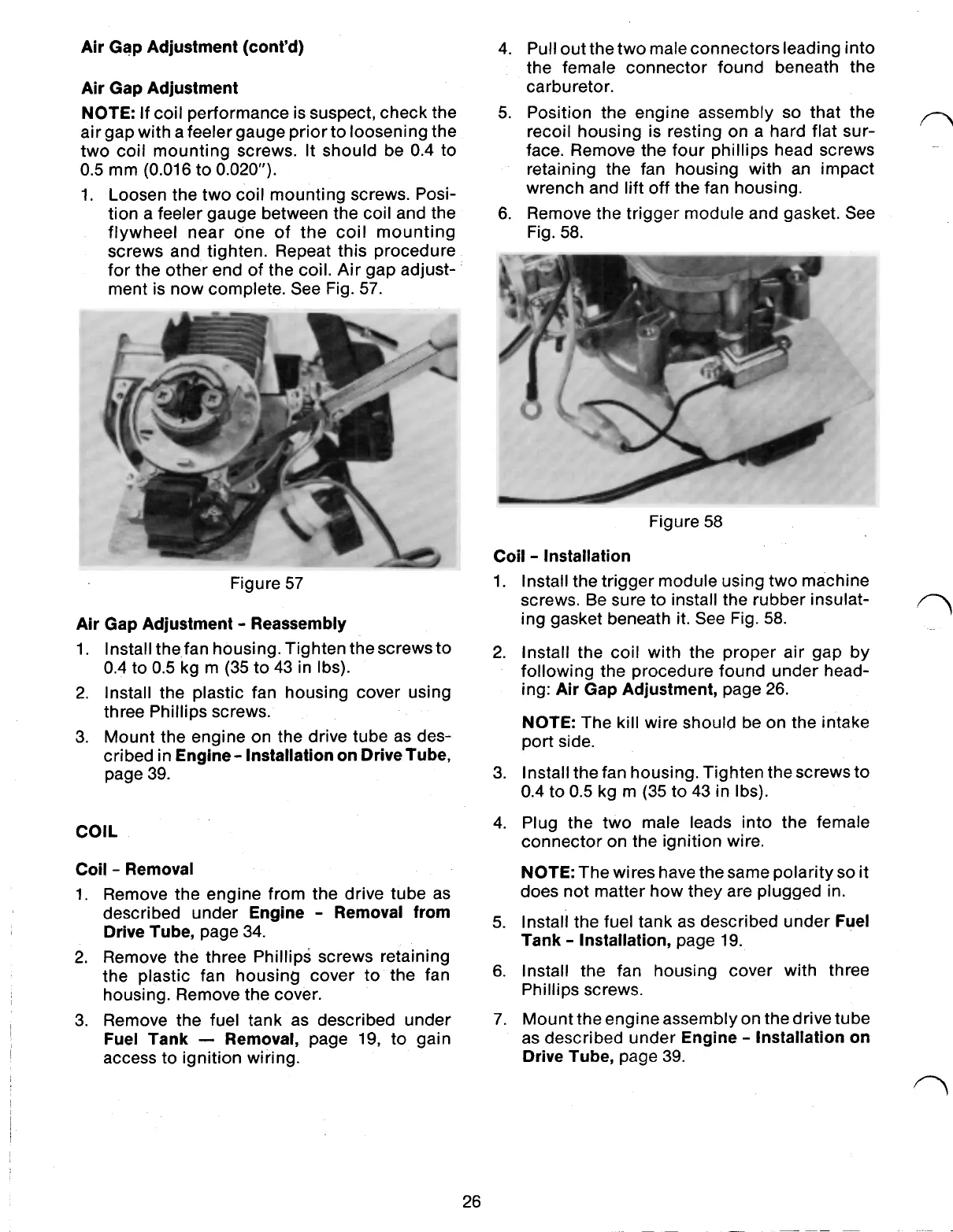
1. Loosen the two coil mounting screws. Posi-
tion a feeler gauge between the coil and the
flywheel near one of the coil mounting
screws and tighten. Repeat this procedure
for the other end of the coil. Air gap adjust-
ment is now complete. See Fig.
57.
Figure
57
Air Gap Adjustment Reassembly
1. Install the fan housing. Tighten the screws to
0.4 to
0.5
kg m (35 to 43 in Ibs).
2.
Install the plastic fan housing cover using
three Phillips screws.
3. Mount the engine on the drive tube as des-
cribed in
Engine Installation on Drive Tube,
page 39.
COIL
Coil Removal
1. Remove the engine from the drive tube as
described under
Engine Removal from
Drive Tube,
page 34.
2.
Remove the three Phillips screws retaining
the plastic fan housing cover to the fan
housing. Remove the cover.
3. Remove the fuel tank as described under
Fuel Tank Removal,
page 19, to gain
access to ignition wiring.
26
4.
Pull out the two maleconnectors leading into
the female connector found beneath the
carburetor.
5.
Position the engine assembly
so
that the
recoil housing is resting on a hard flat sur-
face. Remove the four phillips head screws
retaining the fan housing with an impact
wrench and lift off the fan housing.
6. Remove the trigger module and gasket. See
Fig.
58.
1.
2.
3.
4.
5.
6.
7.
Figure
58
Coil Installation
Install the trigger module using two machine
screws. Be sure to install the rubber insulat-
ing gasket beneath it. See Fig.
58.
Install the coil with the proper air gap by
following the procedure found under head-
ing:
Air Gap Adjustment,
page 26.
NOTE:
The kill wire should be on the intake
port side.
Install the fan housing. Tighten the screws to
0.4 to
0.5
kg m (35 to 43 in Ibs).
Plug the two male leads into the female
connector on the ignition wire.
NOTE:
The wires have the same polarity
so
it
does not matter how they are plugged in.
Install the fuel tank as described under
Fuel
Tank Installation,
page 19.
Install the fan housing cover with three
Phillips screws.
Mount the engineassembly on the drive tube
as described under
Engine Installation on
Drive Tube,
page 39.
 Loading...