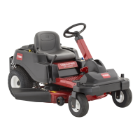
Figure45
1.Sailareaofblade
4.Bladebolt
2.Blade
5.Bladestiffener
3.Curvedwasher
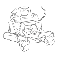
SharpeningtheBlades
1.Usealetosharpenthecuttingedgeatbothends
oftheblade(
Figure46).Maintaintheoriginalangle.
Thebladeretainsitsbalanceifthesameamountof
materialisremovedfrombothcuttingedges.
Figure46
1.Sharpenatoriginalangle
2.Checkthebalanceofthebladebyputtingitona
bladebalancer(
Figure47).Ifthebladestaysina
horizontalposition,thebladeisbalancedandcanbe
used.Ifthebladeisnotbalanced,lesomemetaloff
theendofthesailareaonly(
Figure46).Repeatthis
procedureuntilthebladeisbalanced.
Figure47
1.Blade2.Balancer
InstallingtheBlades
1.Installthebladeontothespindleshaft(Figure45).
Important:Thecurvedpartoftheblademust
bepointingupwardtowardtheinsideofthe
mowertoensurepropercutting.
2.Installthebladestiffener,thecurvedwasher(cupped
sidetowardtheblade)andthebladebolt(
Figure45).
3.Torquethebladeboltto35-65ft-lb(47-88N-m).
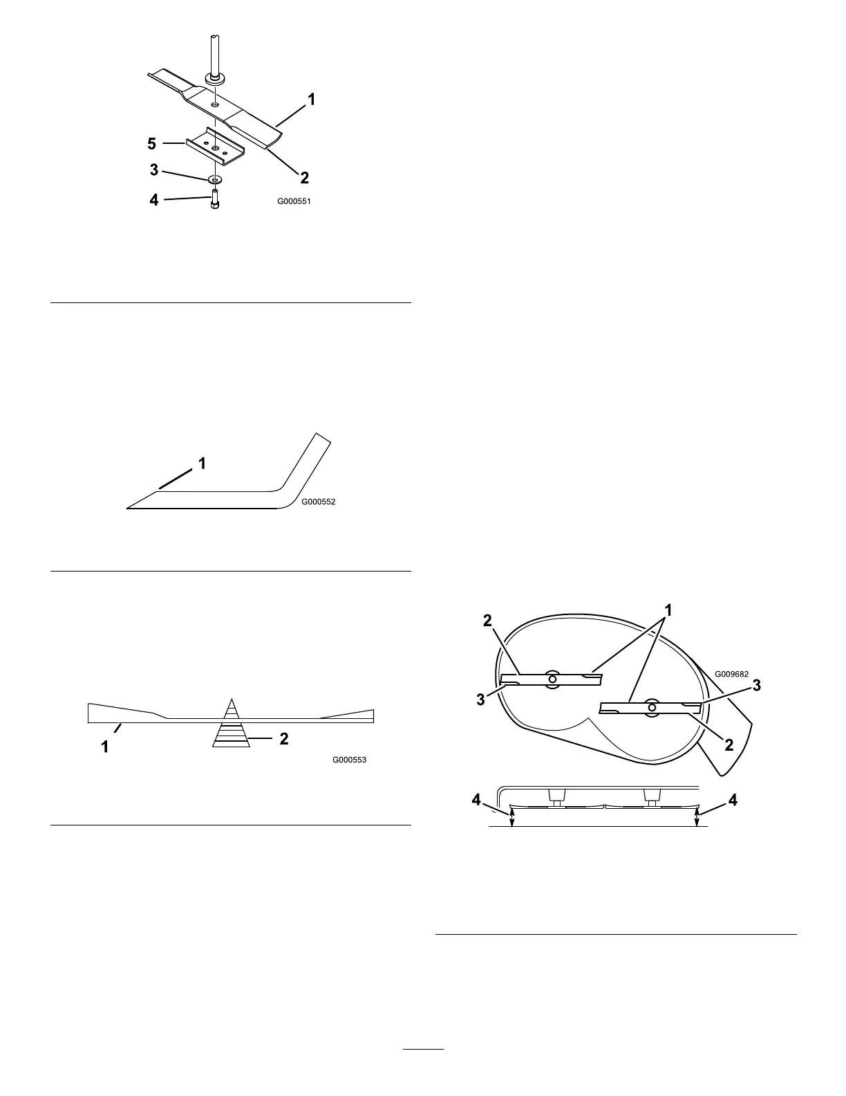
LevelingtheMowerDeck
Checktoensurethemowerdeckislevelanytimeyou
installthemowerorwhenyouseeanunevencuton
yourlawn.
Themowerdeckmustbecheckedforbentblades
priortoleveling;anybentbladesmustberemoved
andreplaced.RefertotheCheckingforBentBlades
procedurebeforecontinuing.
Themowerdeckmustbeleveledside-to-siderstthen
thefronttorearslopecanbeadjusted.
Requirements:
•Themachinemustbeonalevelsurface.
•Allfourtiremustbeproperlyinated.Referto
CheckingtheTirePressureintheDriveSystem
Maintenancesection.
Side-to-SideLeveling
1.Parkthemachineonalevelsurfaceanddisengage
thebladecontrolswitch.
2.Movethemotioncontrolleversoutwardtothe
parkposition,stoptheengine,removethekey,and
waitforallmovingpartstostopbeforeleavingthe
operatingposition.
3.Settheheight-of-cutlevertomiddleposition.
4.Carefullyrotatetheblade(s)sothattheyareallside
toside(Figure48).
Figure48
1.Bladessidetoside
3.Outsidecuttingedges
2.Sailareaofblade4.Measurefromthetipofthe
bladetotheatsurface
here
5.Measurebetweentheoutsidecuttingedgesandthe
atsurface(
Figure48).Ifbothmeasurements
arenotwithin3/16inch(5mm),anadjustmentis
required;continuewiththisprocedure.
35
 Loading...