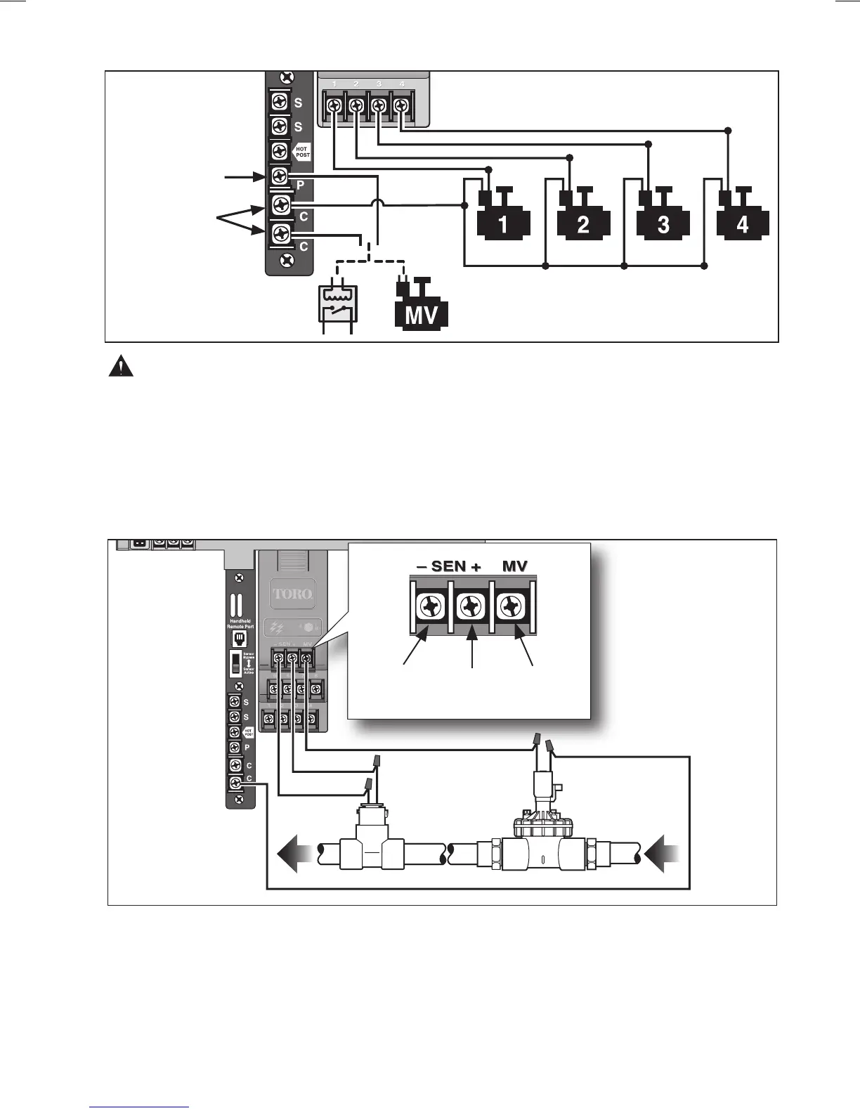
CAUTION: To avoid possible equipment damage, do not connect pump starter directly
to the controller. A 24V, 0.5A (maximum) relay must be used for this connection.
Flow Sensor Connection
1. Route the flow sensor wires into the controller cabinet.
2. Connect the flow sensor wires to the flow-enabled expansion module as follows: Black to
negative (–) and Red to positive (+).
NOTE: Flow Sensor wiring polarity must be correct to enable operation.
3. If the master valve circuit is used, connect either solenoid wire to the MV terminal and the
remaining wire to either common terminal (C).
NOTE: The master valve circuit is controlled by operation of the corresponding expansion
module only.
23
Valve Common Wire
Pump Start Relay
Master Valve
Pump Start/
Master Valve
Valve
Common
Black (–)
Red (+)
Master
Valve
Flow Sensor
Master Valve