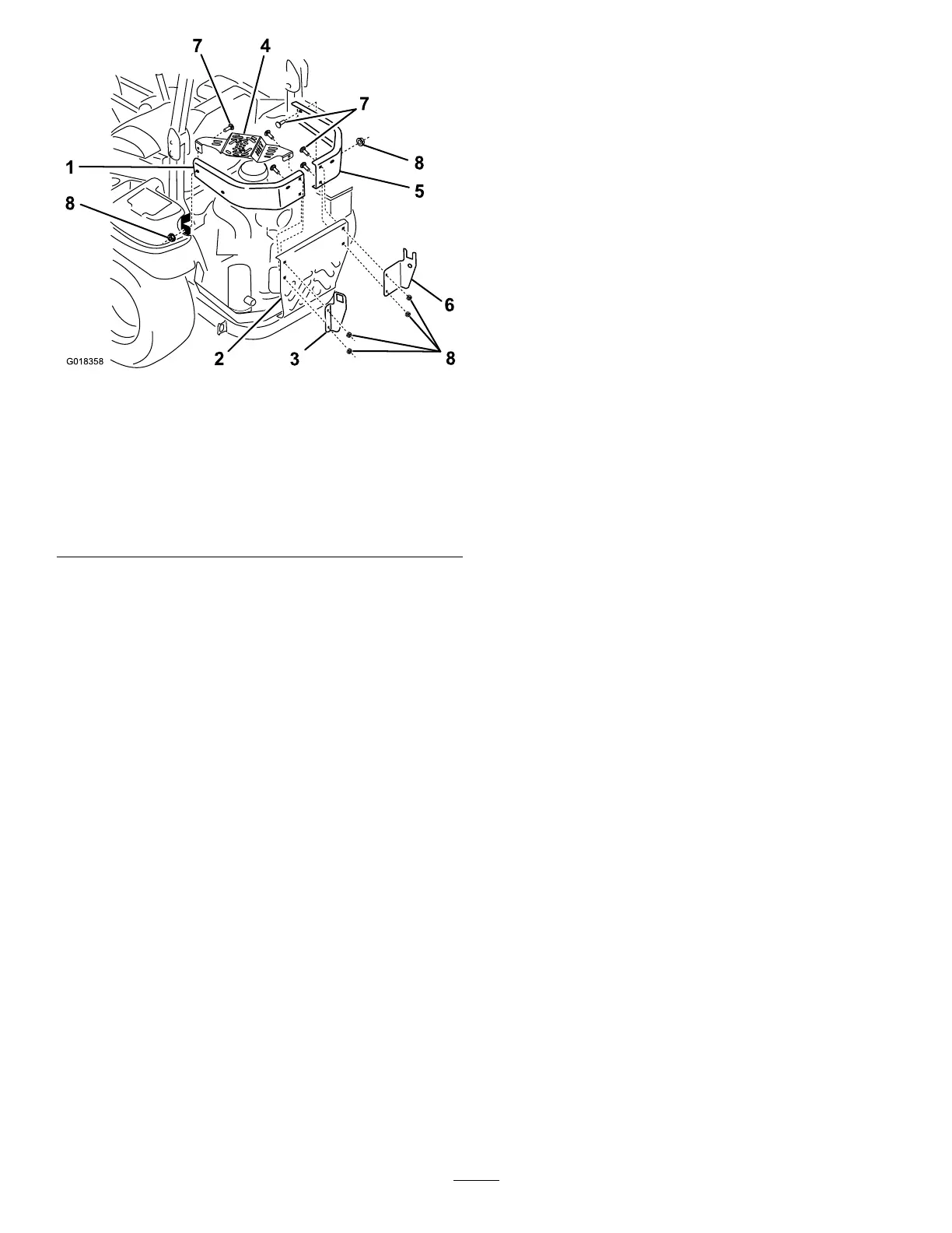
Figure4
SideBumperandBracketInstallation
1.Leftsidebumper
5.Rightsidebumper
2.Centerengineguard6.Rightframe-support
bracket
3.Leftframe-supportbracket7.Carriagebolt(3/8x1-1/4
inches)
4.Mufershield8.Flangenut(3/8inch)
B.Removetheleftbumperandmufershieldfrom
themachine.
Note:Retainthemufershieldforinstallation
withthenewleftsidebumper.
C.Removethenutsandboltssecuringtherightside
bumpertothechassisandcenterengineguard.
Note:Discardthecarriageboltsandangenuts
thatsecuretheoriginalleftandrightsidebumpers
tothemachine.
2.Installthenewleftsidebumperasfollows:
A.Alignthenewleftsidebumperwiththe
forward-mountingpointonthechassisandthe
bumper-mountingpointsonthecenterengine
guard(Figure4).
B.Alignthemountingange(theangewith2
holes)oftheleftframe-supportbrackettotheleft
asshowninFigure4.
C.Aligntheholesoftheleftframe-supportbracket
andthebackholesoftheleftsidebumperwith
theholesinthecenterengineguard(Figure4).
D.Looselysecurethebracketandbumpertothe
centerengineguardatthelowerholewitha
carriagebolt(3/8x1-1/4inches)andaangenut
(3/8inch)(Figure4).
E.Positionthemuferheatshieldwiththemounting
angesinsidetheleftsidebumper(Figure4).
F.Aligntheholesfortheleftframe-supportbracket,
leftsidebumperandmuferguardtotheupper
holeinthecenterengineguard(Figure4).
G.Looselysecurethebracket,bumperandmufer
guardtothecenterengineguardattheupperhole
withacarriagebolts(3/8x1-1/4inches)anda
angenut(3/8inch)(Figure4).
H.Alignthefrontholesintheleftsidebumperand
themuferguardwiththeforward-mounting
pointonthechassis.(Figure4).
I.Securethebumperandguardtothemounting
pointwithacarriagebolt(3/8x1-1/4inches)and
aangenut(3/8inch)(Figure4).
J.Tightenthehardwarethatsecuresthebracket,
bumperandmuferguardtothecenterengine
guard.
3.Installthenewrightsidebumperasfollows:
A.Alignthenewrightsidebumperwiththe
forward-mountingpointonthechassisandthe
bumper-mountingpointsonthecenterengine
guard(Figure4).
B.Alignthemountingange(theangewith2
holes)oftherightframe-supportbrackettothe
leftasshowninFigure4.
C.Aligntheholesoftherightframe-supportbracket
andbackholesoftherightsidebumperwiththe
back,centerengineguard(Figure4).
D.Looselysecurethebracketandbumpertothe
centerengineguardwith2carriagebolts(3/8x
1-1/4inches)and2angenut(3/8inch)(Figure
4).
E.Alignthefrontholeinthenewrightsidebumper
withtheforwardmountingpointonthechassis
(Figure4).
F.Securethebumpertothemountingpointwith
acarriagebolt(3/8x1-1/4inches)andaange
nut(3/8inch)(Figure4).
G.Tightenthehardwarethatsecuresthebracketand
bumpertothecenterengineguard.
7
 Loading...