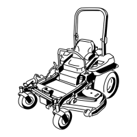
ProductOverview
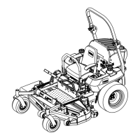
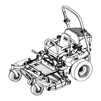
Figure4
1.ZStand
©
6.Fuelcap(bothsides)
2.Height-of-cutlever
7.Parkingbrakelever
3.Motioncontrollever8.Mowerdeck
4.Seatbelt9.Casterwheel
5.Rollbar
Controls
Becomefamiliarwithallthecontrolsbeforeyoustartthe
engineandoperatethemachine(Figure4andFigure5).
Figure5
1.Hourmeter
6.Glowpluglight
2.Ignitionswitch7.EngineT emperaturelight
3.Fuelselectorvalve8.Throttlecontrol
4.Audiblealarm
9.PTOSwitch
5.Glowplugswitch
HourMeter
Thehourmeterrecordsthenumberofhourstheengine
hasoperated.Itoperateswhentheengineisrunning.
Usethesetimesforschedulingregularmaintenance
(
Figure5).
SafetyInterlockIndicators
Therearesymbolsonthehourmeterandtheyindicate
withablacktrianglethattheinterlockcomponentisin
thecorrectposition(
Figure6).
BatteryIndicatorLight
WhentheignitionkeyisinitiallyturnedtotheRun
positionforafewseconds,thebatteryvoltagewillbe
displayedintheareawherethehoursarenormally
displayed.
Thebatterylightturnsonwhentheignitionisturned
onandwhenthechargeisbelowthecorrectoperating
level(
Figure6).
Figure6
1.Safetyinterlocksymbols
3.Batterylight
2.Hourmeter
ThrottleControl
ThethrottlecontrolisvariablebetweenFastandSlow.
BladeControlSwitch(PTO)
Thebladecontrolswitch(PTO)isusedtoengagethe
electricclutchtodrivethemowerbladeswiththemotion
controlleversinthecenter,un-lockedposition.Pullthe
switchuptoengagethebladesandrelease.Todisengage
theblades,pushthebladecontrolswitch(PTO)down.
NeutralLockPosition
Theneutrallockpositionisusedwiththesafetyinterlock
systemandtodetermineneutralposition.
15

 Loading...
