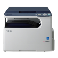
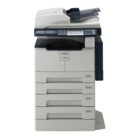
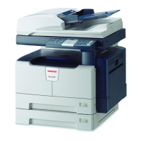
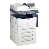
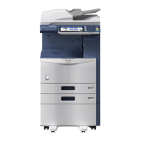
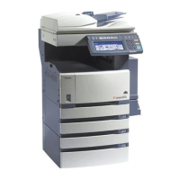
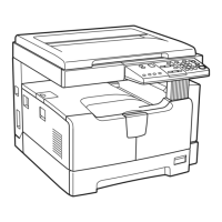
Do you have a question about the Toshiba e-STUDIO166 and is the answer not in the manual?
Precautions and steps for safely transporting and installing the equipment, including weight and handling.
Lists safety-critical parts like breakers, fuses, and batteries that require proper handling.
Advises checking rating plates and cautionary labels for dirt and proper attachment.
Details technical specifications of the e-STUDIO163/166/203/206 series, including copy process and speed.
Lists standard accessories provided with the e-STUDIO163/203 and e-STUDIO166/206 models.
Details the specific accessories included with the e-STUDIO163/203 models.
Details the specific accessories included with the e-STUDIO166/206 models.
Lists optional equipment available for the e-STUDIO series.
Lists consumable supplies such as drum and toner cartridge for the e-STUDIO series.
Diagram illustrating the system configuration and interconnected components.
Provides a list of error codes, their classification, contents, and troubleshooting steps.
Details specific error codes related to paper jams, including paper exit, misfeeding, and cover open jams.
Lists error codes for service calls, categorized by system, fuser, optional communication, and process.
Explains how to enter and use various self-diagnosis modes for checking equipment status.
Details how to check the status of input signals using Test Mode 03.
Details how to check the status of output signals using Test Mode 04.
Procedure for printing embedded test patterns using Test Mode 07.
Procedure for outputting lists of function settings, system settings, and memory dumps.
Procedure for registering, deleting, and confirming access codes and counter values.
Procedure for setting various functions by configuring bits in the function table.
Lists items adjustable in Mode 05, including ADF, image, paper feeding, drive, and scanner.
Lists items adjustable in Mode 08, covering ADF, counter, image, development, scanner, and fuser.
Details items that can be checked in Test Mode 13, such as SRAM, DRAM, CODEC, and button tests.
Procedure for setting the country/region code, typically required after SRAM board replacement.
Procedure for adjusting the auto-toner sensor after replacing the developer material.
Lists adjustment items for image dimensions and their corresponding codes in Adjustment Mode (05).
Details how to adjust paper alignment at the registration roller for various paper types and feed methods.
Covers reproduction ratio and laser writing start position adjustments for printer functions.
Procedure for adjusting secondary scanning laser writing start position per paper source using codes.
Procedure to adjust the primary scanning reproduction ratio using a ruler and test copies.
Procedure to adjust primary scanning image position using a ruler and test copies.
Procedure to adjust secondary scanning reproduction ratio using a ruler and test copies.
Procedure to adjust secondary scanning image position using a ruler and test copies.
Procedure to adjust the top margin by measuring blank area on test prints and using codes.
Procedure to adjust the right margin by measuring blank area on test prints and using codes.
Procedure to adjust the bottom margin by measuring blank area on test prints and using codes.
Adjusts image quality for copying function, including density, gamma slope, and sharpness.
Procedure for adjusting image density for copying function using specific codes and test copies.
Procedure for adjusting gamma slope using specific codes and test copies.
Procedure for adjusting sharpness of copy images using specific codes and test copies.
Sets background peak levels for range correction using specific codes and test copies.
Procedure for adjusting smudged/faint text levels using specific codes and test copies.
Procedure for adjusting image density levels using specific codes and test copies.
Adjusts image quality for printing function, including smudged/faint text and image density.
Procedure for adjusting image density levels for printing function using specific codes.
Adjusts image quality for scanning function, including density, sharpness, and range correction.
Procedure for adjusting scanning image density using specific codes and test copies.
Procedure for adjusting scanning image sharpness using specific codes and test copies.
Adjusts background/text peak values in range correction for scanning using specific codes.
Procedure for adjusting main charger, developer bias, transfer charger, and separation charger outputs.
Step-by-step instructions for installing the high-voltage transformer jig correctly.
Diagram showing the connection setup for developer bias adjustment using test equipment.
Diagram showing the connection setup for main charger adjustment using test equipment.
Diagram showing connection setup for transfer/separation charger adjustment with test equipment.
Instructions for operating the high-voltage transformer adjustment using digital testers and tables.
Notes and precautions for adjusting developer bias, including potential issues with low bias.
Items to check before adjusting transfer output, including charger wire and process unit status.
Items to check before adjusting separation output, and notes on poor paper separation/transfer.
Covers CIS unit replacement, drive belt tension, and scan motor adjustment.
Information on replacing the CIS unit, handling precautions, and error recovery procedures.
Procedure for adjusting the tension of the CIS unit drive belt-1 when installing it.
Procedure for adjusting the tension of the CIS unit drive belt-2 with a belt tension jig.
Procedure for adjusting sheet sideways deviation caused by paper feeding.
Procedure for adjusting the doctor-to-sleeve gap using a doctor-sleeve jig and specific codes.
Covers ADF position, height, skew, leading edge, horizontal, and copy ratio adjustments.
Procedure for adjusting the ADF position if it is not installed correctly, including checking steps.
Procedure for checking and adjusting the ADF height, including gap tolerance specifications.
Procedure to adjust skew by shifting the aligning plate based on image inclination.
Procedure to adjust the leading edge position of copies by comparing chart and copy images.
Procedure to adjust horizontal image position by checking center line alignment on copies.
Procedure to adjust copy ratio by checking image dimension against a chart and using codes.
Procedure to adjust the bracket position of the ADF opening/closing sensor.
Details the timing for preventive maintenance, preparation steps, and post-maintenance checks.
Lists components and tasks for equipment overhauling based on usage time or page count.
Checklists for various machine parts including scanner, laser unit, feed unit, and ADF.
Lists the contents of the Preventive Maintenance kits for different machine parts.
Lists all jigs required for maintenance procedures with their corresponding page and item numbers.
Lists the types of grease used, their part names, volumes, and containers.
Guidelines for storing toner, developer, drums, blades, rollers, and paper under specific conditions.
Detailed instructions for checking and cleaning the photoconductive drum, including handling precautions.
Precautions and procedure for checking and cleaning the drum cleaning blade edge.
Handling precautions, checking, and cleaning procedures for fuser and pressure rollers.
Guides for diagnosing and resolving issues based on specific error codes displayed by the equipment.
Troubleshooting steps for paper jams related to exit sensor, registration sensor, and pickup solenoid.
Troubleshooting steps for paper misfeeding, checking registration sensor and bypass pickup solenoid.
Troubleshooting for ADU cover open errors, checking 24V supply and cover sensor switches.
Troubleshooting for ADF transport jams, checking rollers, sensors, and ADF boards.
Troubleshooting for polygonal motor and H-Sync detection errors in the laser optical unit.
Covers firmware update errors, high-voltage transformer abnormalities, and backup counter issues.
Steps to diagnose and prescribe solutions for issues with image density and gray balance.
Steps to diagnose and prescribe solutions for background fogging issues in images.
Troubleshooting steps for Moire patterns and lack of sharpness in printed images.
Troubleshooting steps for toner offset issues, checking density, fuser unit, paper, and developer.
Troubleshooting steps for blurred images, checking paper, scanner, drum, and ozone exhaust.
Troubleshooting steps for poor fusing issues, checking heater, pressure, temperature, and paper.
Troubleshooting steps for blank copies, checking transfer charger wire, high-voltage transformer, and drum.
Troubleshooting steps for solid copy issues, checking exposure lamp, main charger, and drum.
Troubleshooting for white banding, checking laser optical unit, main charger grid, and developer unit.
Troubleshooting for white banding, checking main charger, drum, developer unit, and drive system.
Troubleshooting for skewed images, checking drawer installation, feed roller, and aligning amount.
Troubleshooting for black banding, checking shading correction plate, main charger, and cleaner.
Troubleshooting for black banding, checking needle electrode, fuser roller, and drum.
Troubleshooting for white spots, checking toner density, doctor-sleeve gap, and developer material.
Troubleshooting steps for poor image transfer, checking paper, transfer charger, and registration roller.
Troubleshooting for uneven image density, checking main charger, transfer charger, and developer unit.
Troubleshooting for faded images, checking toner, toner motor, and high-voltage transformer.
Troubleshooting for image dislocation, checking registration roller, clutch, and aligning amount.
Troubleshooting for jittering images, checking toner image, rollers, drum, and drive system.
Troubleshooting for poor cleaning, checking developer material, cleaner, fuser unit, and toner recovery.
Troubleshooting for uneven light distribution, checking original glass, main charger, and scanner.
Troubleshooting for blotched images, checking paper type, separation and transfer charger.
Procedures for replacing MAIN and SRAM boards, including data recovery steps.
Procedure for replacing the MAIN board, including installing SRAM and updating ROMs.
Procedure for replacing the SRAM board, including RAM clear and copying counter values.
Instructions for updating firmware using a download jig connected to the equipment.
Procedure for updating firmware using the PWA-DWNLD-350-JIG download jig.
How to confirm updated data versions in Setting Mode (08) after firmware update.
Procedure for writing firmware data to the download jig using a ROM writer and adapter.
Precautions for writing data, including voltage settings, address settings, and rotary switch use.
Procedure for updating firmware using the K-PWA-DLM-320 download jig on ADF control PC board.
Instructions for updating firmware using TOSHIBA Viewer software on a PC.
Procedure to update firmware using the software update tool via USB cable.
Lists the system requirements for operating the software update tool, including OS and USB version.
Steps for preparing and precautions before using the software update tool, including driver installation.
Step-by-step guide to update firmware using the software update tool via USB cable.
Details the output channels for the main switch line and the cover switch line of the power supply.
Table listing fuses for various components, their voltage, board/unit, part, and fuse type.
Schematic diagram showing the configuration and connections of the power supply unit components.
Diagram illustrating the AC wire harness connections for various units and components.
Detailed DC wire harness diagram for the e-STUDIO163/203 MAIN and SRAM boards.
Detailed DC wire harness diagram for the e-STUDIO166/206 MAIN and SRAM boards.
| Brand | Toshiba |
|---|---|
| Model | e-STUDIO166 |
| Category | All in One Printer |
| Language | English |
