No
Yes
Yes
No
Yes
No
Yes
No
Yes
No
Yes
No
No
Yes
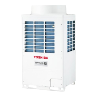
[E04]
No
Yes
No
Yes
Yes
No
Yes
No
No
Yes
No
Yes
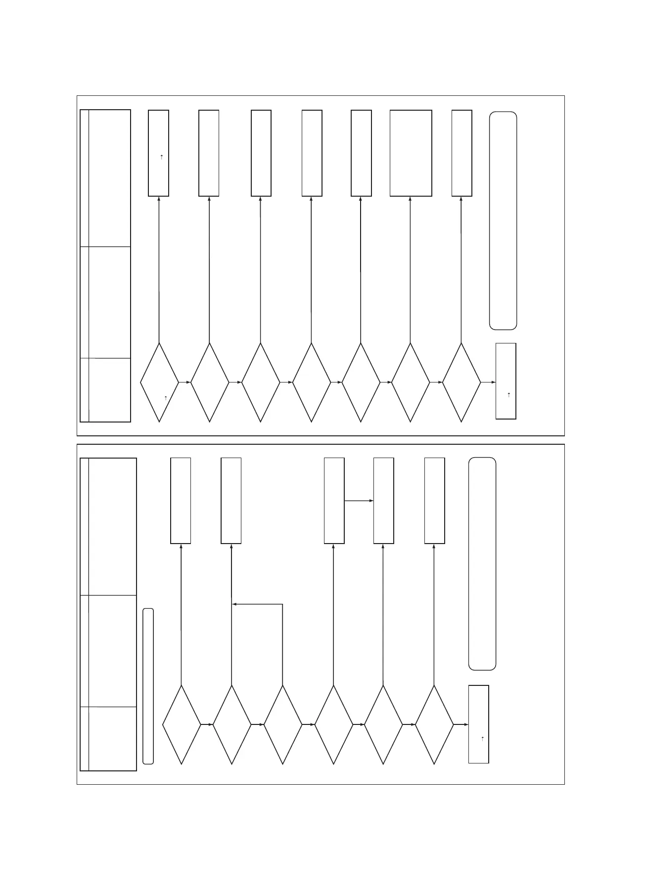
[E06]
Sub-code: No. of indoor units which received signals normally
esuaCedoc kcehC Check code name esuaCedoc kcehC Check code name
Decreased number of indoor units
Indoor/Outdoor communication
circuit trouble
(Detected at indoor side)
1. Communication lines (U1, U2) connection trouble
between indoor and outdoor
2. Communication connector's connection trouble on
indoor unit, trouble on P.C. board
3. Communication connector's connection trouble on
outdoor unit, trouble on I/F board
4. Power supply of indoor unit (Is power turned on?)
1. Power of outdoor unit was firstly turned on.
2. Connection trouble of communication line
between indoor and outdoor
3. Terminator resistor setup trouble on
communication between indoor and outdoor
4. Address setup trouble
Is there no
miswiring/disconnection
on communication line
between indoor and
outdoor?
Was power turned on
in order of indoor unit
outdoor unit?
Is connection
(U1/U2 terminals) of
indoor/outdoor inter-unit
wire normal?
Is connector
connection from U1/U2
terminals of indoor/outdoor
inter-unit wire
normal?
Is the terminator resistor
setup of outdoor unit
normal?
Is power applied to fuse
(F03) on indoor P.C.
board?
Is address setup correct?
Is there no noise, etc?
Is connection
of CN40 connector on
indoor P.C. board
normal?
Is connection of CN01
connector on outdoor I/F
P.C. board normal?
Is power of indoor unit
turned on?
Did a power failure
occur?
Is there no noise, etc?
Correct communication line.
Turn on power again in order
of indoor unit
outdoor unit.
Correct inter-unit wire.
Correct connector connection.
Correct the terminator resistor
setup.
Set up address again.
Check noise, etc, and
eliminate it if any.
Check connection of inter-unit
wire between indoor and outdoor
is correct, and then connect
communication line connector on
indoor P.C. board (CN40) to
CN44 (EMG).
Correct wiring or connector.
Turn on power of indoor unit.
Clear the check code.
Check noise, etc, and eliminate
it if any.
Check indoor P.C. board.
Failure Replace
Check indoor P.C. board.
Failure Replace
(NOTE)
1. When signal is not sent for a certain period from the indoor unit which has
used to send signals normally, [E06] is displayed.
For details, refer to “8-5. Troubleshooting in Test Operation”.
− 164 −

 Loading...