– 125 –
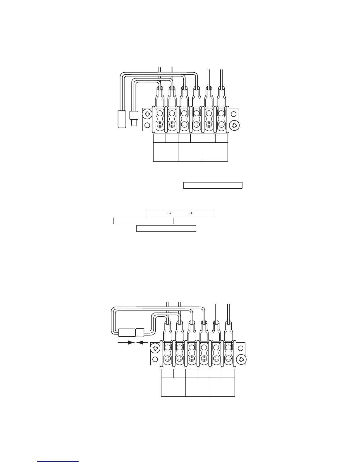
2 Be sure to disconnect the relay connectors between the [U1U2] and [U3U4] terminals on all the
header outdoor units that will be connected to the central control. (Factory default: disconnected)
3 Turn on indoor units first, and then turn on outdoor units.
4 About 1 minute after turning the power on, confirm that the 7-segment display on the interface
. setacidni tinu roodtuo redaeh eht fo draob .C.P
5 Press SW 15 to start the automatic address setting.
(It may take up to 10 minutes (normally about 5 minutes) to complete one line’s setting.)
6 . setacidni yalpsid tnemges-7 ehT
.yalpsid eht no gnihsalf strats ,noitacidni eht retfA
si gnittes eh
t ,yalpsid eht no til sniamer , dna spots gnihsalf eht nehW
complete.
7 Repeat steps 4 to 6 for other refrigerant lines.
8 After completing address setting of all systems, turn off dip switch 2 of SW30 on the interface P.C.
boards of all the header outdoor units connected to the same central control, except the unit that
has the lowest address.
(For unifying the termination of the wiring for the central control of indoor and outdoor units)
9 Connect the relay connectors between the [U1, U2] and [U3, U4] terminals of the header outdoor
unit of each refrigerant line.
U1 U2 U3 U4 U5 U6
2
TO
INDOOR
UNIT
TO
CENTRAL
CONTROL
LER
TO
OUTDOOR
UNIT
U. 1. L08 (U. 1. flash)
Auto 1 Auto 2 Auto 3
U. 1. - - - (U. 1. flash)
U. 1. - - - (U. 1. light)
U1 U2 U3 U4 U5 U6
9
TO
INDOOR
UNIT
TO
CENTRAL
CONTROL
LER
TO
OUTDOOR
UNIT
 Loading...


