– 42 –
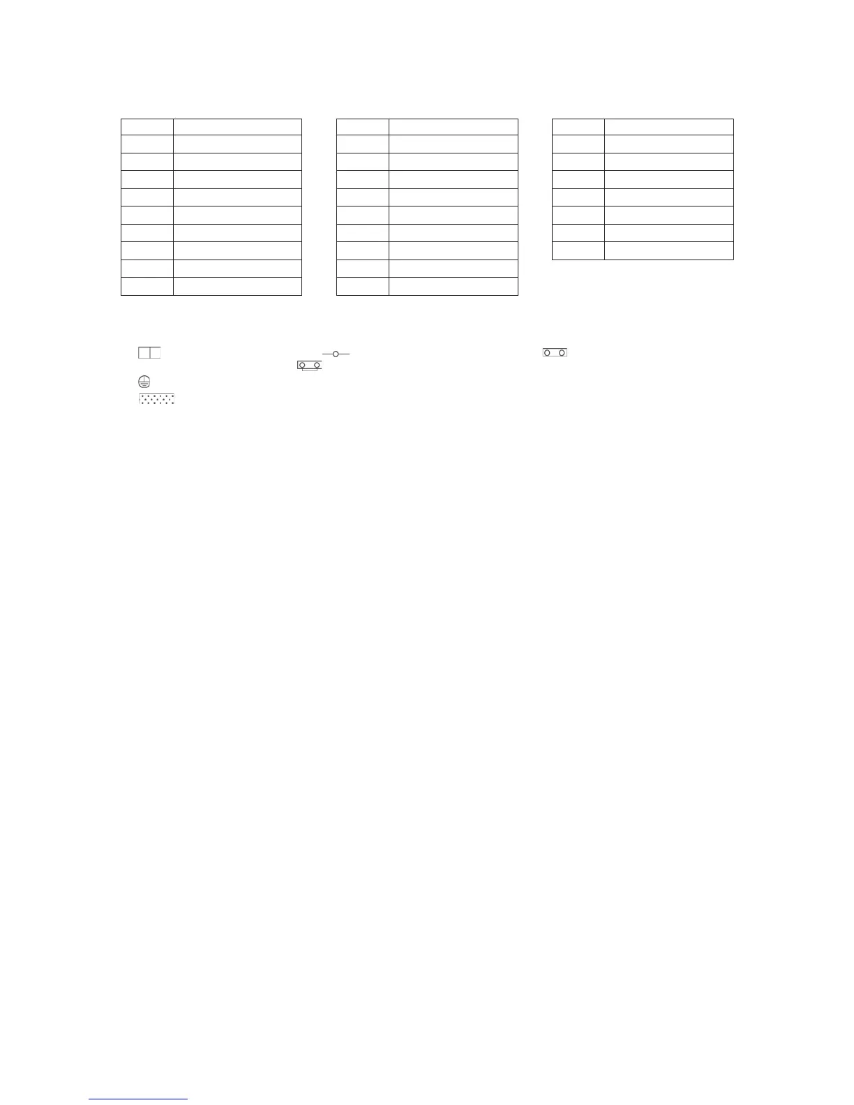
(1) The dotted line represents a wire procured locally, and the dashed line represents an option sold
separately.
(2) represents a terminal block, represents a connection terminal, represents a connector on
the printed circuit board and represents a short circuit connector.
(3) represents a protective earth.
(4) represents a printed circuit board.
(5) Using a no voltage a-contact input of the external input (option), the following operations are available.
Between 1 and 2 : Selecting the remote controller operation (Invalid / Valid)
Between 1 and 3 : Adjusting the fan speed (Low / High)
Between 1 and 5 : Operation (ON / OFF)
Use a microcurrent contact (DC 12 V, 1 mA). In addition, ON / OFF operation is possible when using a
voltage of DC 12 V or 24 V.
(6) Orange wire (High) is connected as factory default. To switch to “Extra High”, connect black wire's
connector instead of orange.
eman straPedoCeman straPedoCeman straPedoC
evlav citengam noisserpmoceD1VMDrosnes AFTAFTrotcennoC**NC
F01 Fuse (printed circuit board)
TCJ, TC1, TC2
evlav gnitaludom esluPVMProsnes lioc roodnI
hctiws piD107WS)ecruos rewop( kcolb lanimreT1BT)rotom( esu
F20F
)noitacinummoc( kcolb lanimreT2BTrotom gniylppus riA1MF
43F11, 43F12
Relay for air supplying motor
)tuptuo lanretxe( kcolb lanimreT3BTrotom gnitsuahxe riA2MF
43F21, 43F22
Relay for air exhausting motor
)tatsidimuh( kcolb lanimreT4BTrotom repmaDMAD
RY701, RY702
Relay for air supplying motor
)evlav citengam( kcolb lanimreT5BTrosnes ARTART
RY704, RY705
Relay for air exhausting motor
hctiws taolF1SFrosnes AOTAOT
evlav citengaM1VMrosnes ASTAST
 Loading...


