– 2 –
CONTENTS
1. DESCRIPTION .................................................................................................................3
2. SPECIFICATIONS............................................................................................................ 4
3. CONSTRUCTION VIEWS .............................................................................................. 11
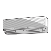
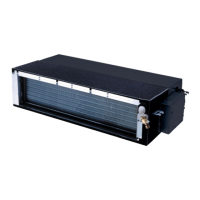
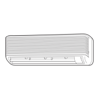
3-1. Indoor Unit ................................................................................................................................ 11
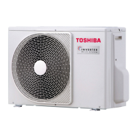
3-2. Outdoor Unit ............................................................................................................................. 12
4. REFRIGERANT CYCLE DIAGRAMS ............................................................................ 14
5. WIRING DIAGRAM ........................................................................................................ 17
6. SPECIFICATIONS OF ELECTRICAL PARTS ............................................................... 19
6-1. Indoor Unit ................................................................................................................................ 19
6-2. Outdoor Unit ............................................................................................................................. 20
7. MICROCOMPUTER BLOCK DIAGRAMS ..................................................................... 21
8. OPERATION DESCRIPTIONS....................................................................................... 23
8-1. FAN ONLY Operation ............................................................................................................... 23
8-2. COOL Operation ....................................................................................................................... 23
8-3. DRY Operation .......................................................................................................................... 24
8-4. HEAT Operation........................................................................................................................ 25
8-5. AUTO Operation ....................................................................................................................... 26
8-6. ECONO. Mode ........................................................................................................................... 27
8-7. Current Limit Control............................................................................................................... 27
8-8. High-Temperature Limit Control............................................................................................. 28
8-9. Low-Temperature Limit Control (Cooling Operation) .......................................................... 28
8-10. Cool Airflow Prevention Control (Heating Operation) ......................................................... 29
8-11. Defrost Operation..................................................................................................................... 29
8-12. Auto Restart Function ............................................................................................................. 31
8-13. Operation Control of Following Outdoor Unit....................................................................... 33
9. TROUBLESHOOTING CHART...................................................................................... 34
9-1. What to be Prechecked First................................................................................................... 34
9-2. Primary Judgement of Trouble Sources ................................................................................ 36
9-3. Troubleshooting Flowcharts ................................................................................................... 40
9-4. How to Check the Remote Control (Including the Indoor P.C. Board) ............................... 47
10. PART REPLACEMENT.................................................................................................. 52
10-1. Indoor Unit ................................................................................................................................ 52
10-2. Microcomputer ......................................................................................................................... 54
10-3. Outdoor Unit ............................................................................................................................. 55
11. CAUTIONS ON REPLACEMENT OF P.C. BOARD ASSEMBLY ................................... 64
12. EXPLODED VIEWS AND PARTS LIST ......................................................................... 65
12-1. Indoor Unit (1)........................................................................................................................... 65
Indoor Unit (2)........................................................................................................................... 66
Indoor Unit (3)........................................................................................................................... 67
12-2. Outdoor Unit ............................................................................................................................. 68
 Loading...