– 25 –
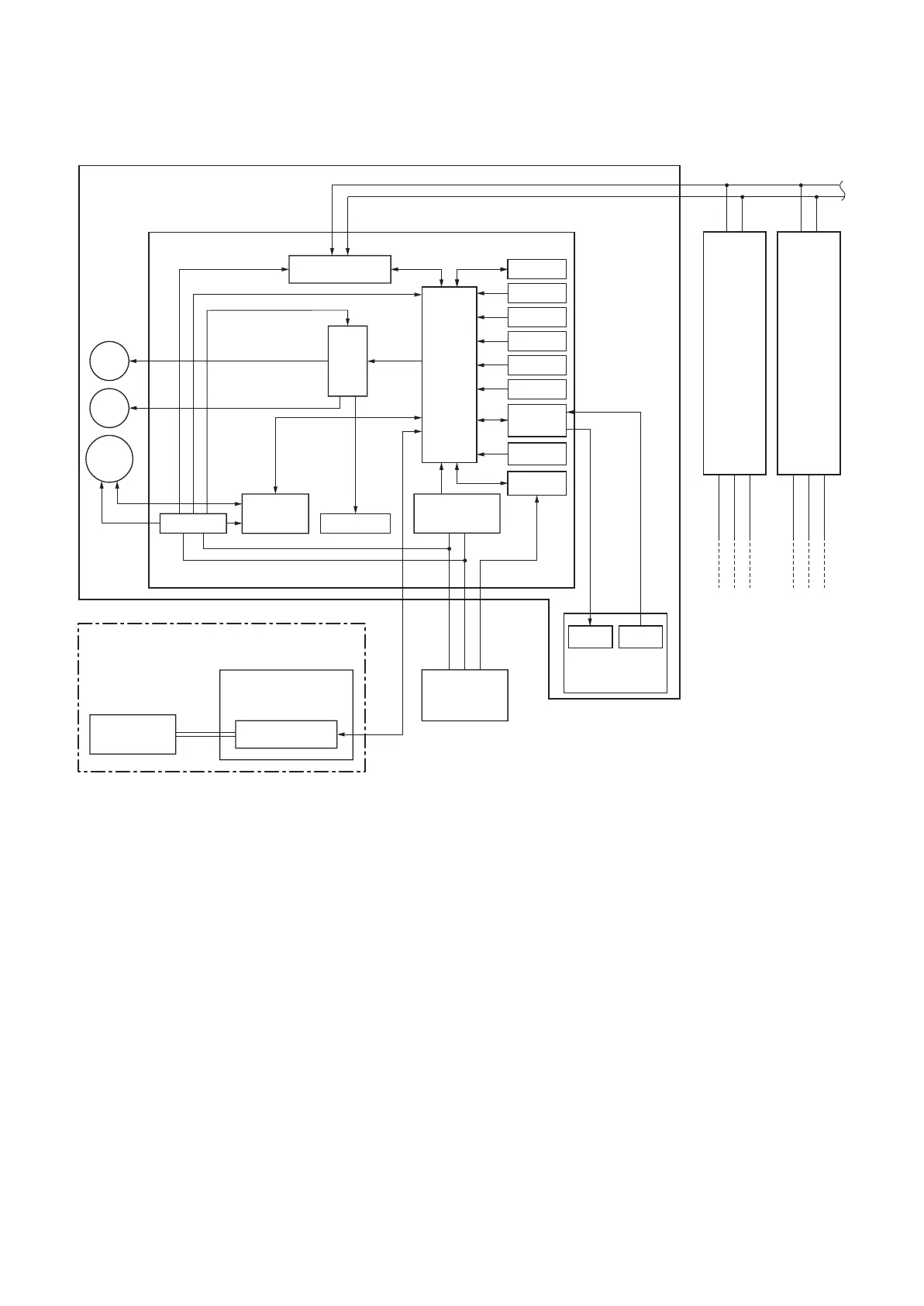
5-1-2. Connection of Wireless Remote Controller Kit
Central controller
(Option)
P.C. board
(MCC-1440)
* Case of “1:1 model” connection interface (Option)
Outdoor unit
Outdoor unit
321
321
321
∗1 Up to 16 units (TU2C-Link) or 8 units (TCC-Link) can
be connected.
∗2 The "1:1 model" connection interface is mounted to
only 1 unit. "1:1 model"connection interface is mounted
to the header unit.
Same as left
∗2
#3
(Follower)*1
A B
Same as left
∗2
#2
(Follower)*1
A B
Indoor unit
#1 (Header) *1
Indoor control P.C. board (MCC-1643)
Louver
motor
Drain
pump
Indoor
fan motor
Driver
DC12V
DC5V
DC20V
AB
Remote controller
communication circuit
Power circuit
DC280V
Fan motor
control circuit
TCC-LINK
communication circuit
AC
synchronous
signal input circuit
Outdoor unit
321
Uh (U3)
Uh (U4)
CPU
EEPROM
TA sensor
TC sensor
TCJ sensor
Float input
HA
Occupancy
sensor
Serial send/
receive circuit
Application
control kit
LED
Receiver
Unit
Outside
output
Start/Alarm
Wireless Remote
Controller Kit