– 26 –
5-1-3. Connection of Both Wired Remote Controller and Wireless Remote Controller Kit
Wired remote controller
(Max. 2 units)
Central controller
(Option)
P.C. board
(MCC-1440)
* Case of “1:1 model” connection interface (Option)
Outdoor unit
Outdoor unit
321
321
321
∗1 Up to 16 units (TU2C-Link) or 8
units (TCC-Link) can be connected.
∗2 The "1:1 model" connection
interface is mounted to only 1 unit.
"1:1 model"connection interface is
mounted to the header unit.
∗3 In the left system, set the wireless
remote controller side as the
follower remote controller when
using the wired remote controller
as the header remote controller.
Same as left
∗2
#3
(Follower)*1
A B
AB
AB
Same as left
∗2
#2
(Follower)*1
A B
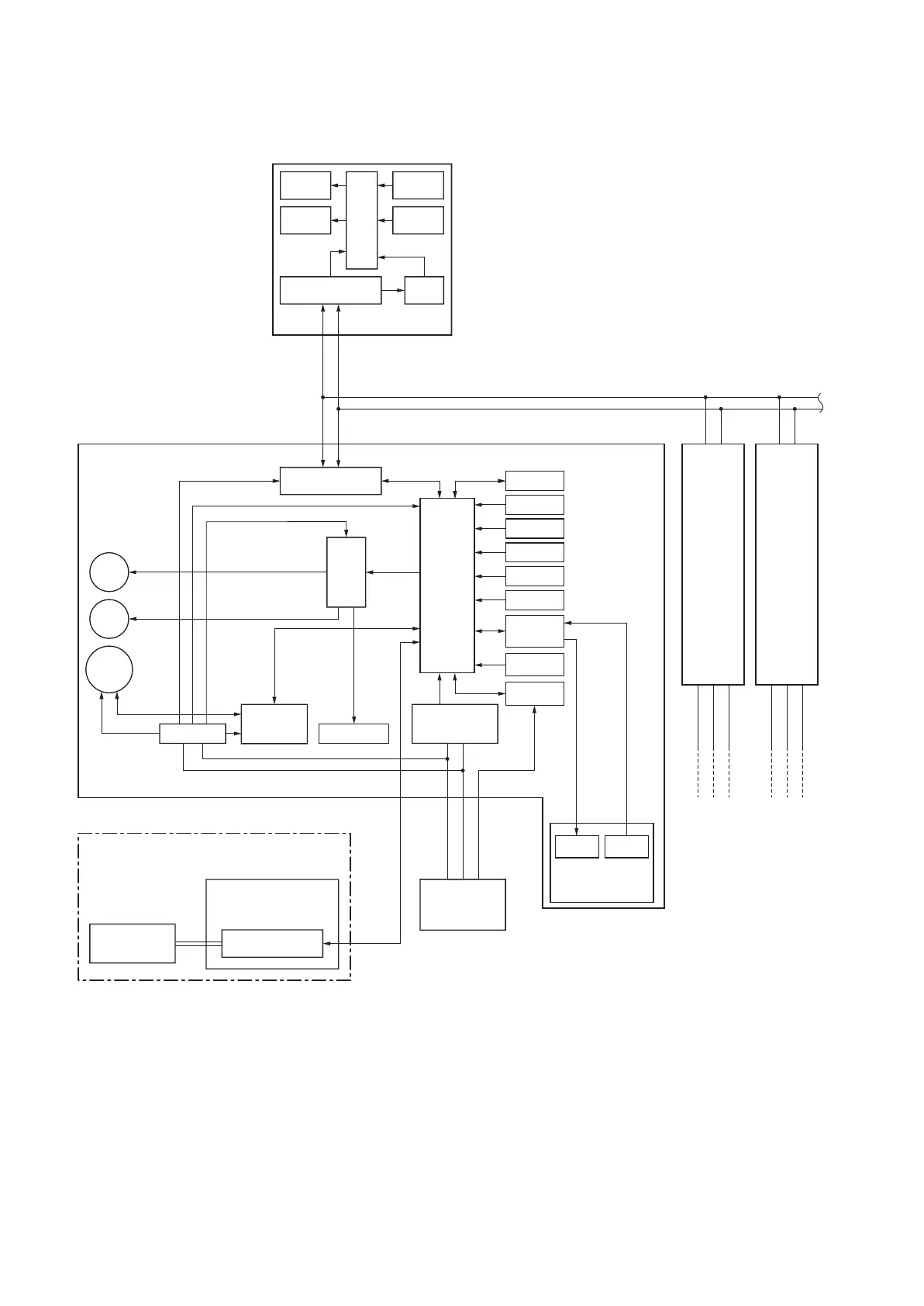
DC5V
Indoor control P.C. board (MCC-1643)
Louver
motor
Drain
pump
Indoor
fan motor
Driver
DC12V
DC5V
DC20V
Remote controller
communication circuit
Display
LCD
Function
setup
Key
switch
CPU
Display
LED
Power
circuit
Remote controller
communication circuit
Power circuit
DC280V
Fan motor
control circuit
TCC-LINK
communication circuit
AC
synchronous
signal input circuit
Outdoor unit
321
U3
U4
CPU
EEPROM
TA sensor
TC sensor
TCJ sensor
Float input
HA
Occupancy
sensor
Serial send/
receive circuit
Application
control kit
Outside
output
Start/Alarm
LED
Receiver
Unit
Wireless Remote
Controller Kit
Indoor unit
#1 (Header) *1
 Loading...