Do you have a question about the Toshiba Satellite C800 and is the answer not in the manual?
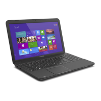
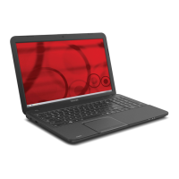
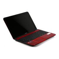
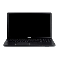
Lists the main features and specifications of the Satellite C800/C845/L800/L840/L845 laptops.
Details the specifications, dimensions, and types of 2.5-inch HDDs used in the system.
Explains the different keyboard layouts (US, UK, JAPAN) and provides illustrations.
Covers the TFT Liquid Crystal Display module, its resolution, and color capabilities.
Describes the main battery and RTC battery, including their specifications.
Introduces troubleshooting, lists covered FRUs, and references other chapters.
Guides the user through a flowchart to identify troubleshooting steps.
Provides procedures to troubleshoot power supply issues, including checks and replacements.
Outlines steps to diagnose and resolve system board malfunctions.
Describes procedures for troubleshooting the 2.5-inch Hard Disk Drive.
Covers troubleshooting steps for the computer's display issues.
Explains how to use the diagnostic software and lists available tests.
Guides users through the process of running diagnostic programs.
Describes the Memory Test and its subtests.
Explains the Keyboard Test and its subtests.
Covers the Display Test and its various subtests.
Outlines the Hard Disk Test and its subtests.
Lists common error codes and their meanings for diagnostic tests.
Introduces the chapter on removing and replacing Field Replaceable Units (FRUs).
Lists critical safety instructions for disassembling and working on the computer.
Lists the necessary tools and ESD equipment for disassembly and assembly.
Details the procedure for removing and installing the battery pack.
Explains how to remove and install the Hard Disk Drive (HDD).
Explains how to remove and install the keyboard.
Details the procedure for removing and installing the display assembly.
Details the procedure for removing and installing the system board.
Provides instructions for removing and installing the LCD unit.
Lists essential precautions for safely handling the LCD module during installation/disassembly.
Shows the layout and component locations on the system board (front view).
Illustrates the layout and connectors of the 3V Touch Pad board.
Shows the layout and connectors for the 5V Touch Pad board.
Illustrates the layout and connectors of the BY4 Touch Pad board.
Displays the layout and connectors of the Power Board.
Details the pin assignments for the HDMI connector.
Lists pin assignments for the LCD connector.
Details pin assignments for the SATA HDD connector.
Provides pin assignments for the keyboard connector.
Lists scan codes for various keys in different modes and with modifier keys.
Shows the pinout for the RGB monitor ID wraparound connector.
Illustrates the wiring diagram for the LAN loopback connector.
| Optical Drive | DVD SuperMulti Drive |
|---|---|
| Processor | Intel Core i3 |
| RAM | Up to 8GB DDR3 |
| Storage | 500GB HDD |
| Display | 1366 x 768 |
| Graphics | Intel HD Graphics |
| Operating System | Windows 7 |
| Connectivity | Wi-Fi 802.11 b/g/n, Bluetooth 4.0 |
| Ports | HDMI, VGA, RJ-45 |
| Battery | 6-cell Lithium-ion |