2-4 User’s Manual
The Grand Tour
Backside
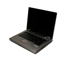
Figure 2-4 shows the computer’s back panel.
Figure 2-4 The backside of the computer
External monitor
port
This 15-pin port lets you connect an external
video display.
Universal
Serial Bus
(USB 2.0) ports
Two Universal Serial Bus ports are on the left
side. The ports comply with the USB 2.0
standard, which enables data transfer speeds 40
times faster than the USB 1.1 standard (The
ports also support USB 1.1.).
Keep foreign objects out of the USB connectors. A pin or similar object can
damage the computer’s circuitry.
Operation of all functions of all USB devices has not been confirmed.
Some functions might not execute proper
ly .
Video-out jack
Modem jack
DC IN 15V
Link indicator
(green)
LAN active
indicator (orange)
LAN jack
Video-out jack Plug an S-Video cable into this jack for video-out.
The S-Video cable carries video signal.
Modem jack In areas where an internal modem is installed as
standard equipment, there is a modem jack that
lets you use a modular cable to connect the
modem directly to a telephone line.
■ In case of a lightning storm, unplug the modem cable from the
telephone jack.
■ Do not connect the modem to a digital telephone line. A digital line will
damage the modem.

 Loading...