Appendix1. Ethernet Control LAN Network Construction Guide
23
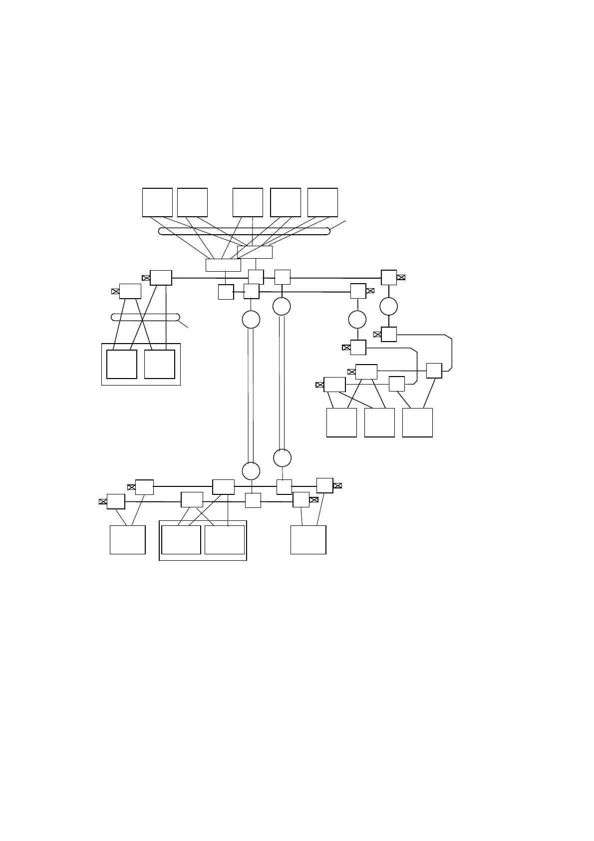
An Example of TOSDIC-CIE DS System Configuration
The following is an example of network configuration for the TOSDIC-CIE DS system.
Terminator
TR
TR
TR
TR
TR
TR
RP
RP
ORP
ORP
ORP
ORP
TR TR
TR
TR
TR
TR
TR
TR
TR
TR
TR
TR
TR
MTR
MTR
TR
10BASE-5 (Coaxial Cable)
(Maximum 500m)
Cable Segment
10BASE-T (Twisted Pair Cable)
(Maximum 100m)
Link Segment
HUB
DPCS
Emulator
Primary
DPCS
Emulator
Secondar
SVR-DS
Secondar
y
PCS-DS
PCS-DSPCS-DS
PCS-DSPCS-DS
OIS-DS OIS-DSOIS-DSSVR-DS
Primary
TR : Transceiver
MTR : Multiport Transceiver
RP : Electric Repeater
ORP : Optical Repeater
HUB : Hub
10BASE5
(Coaxial Cable)
(Maximum 500m)
Cable Segment
10BASE5
(AUI Cable)
(Maximum 15m)
10BASE-5 (Coaxial Cable)
(Maximum 500m)
Cable Segment
DPCS
Emulator
Primary
DPCS
Emulator
Secondary
Figure A1.4 An Example of TOSDIC-CIE DS System Configuration
 Loading...


