Appendix2. The diffrence between DPCS and DPCS Emulator
45
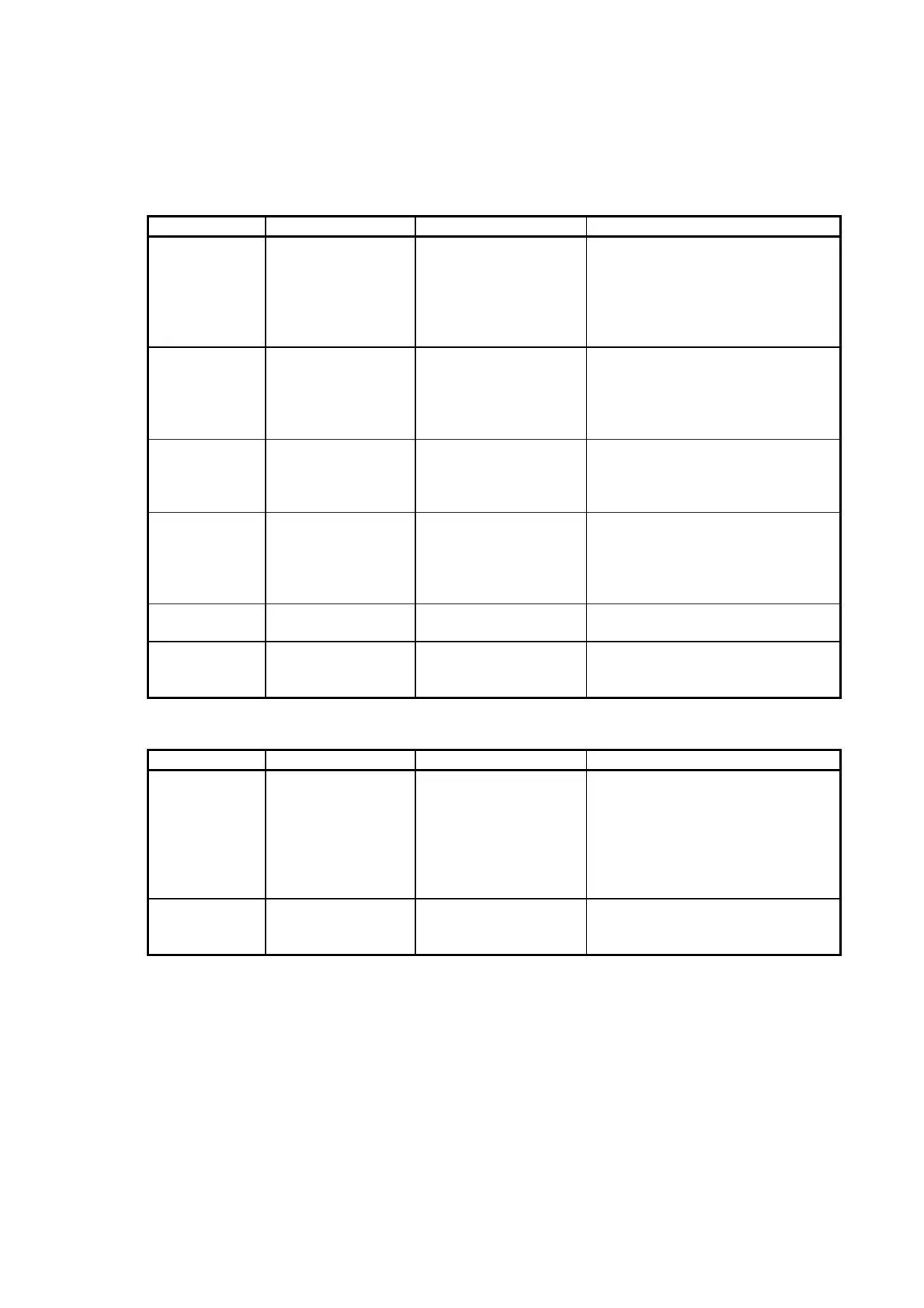
Item DPCS DPCE Emulator Notes
Input of Tc VAMPX1 and
linearizing poly line
table.
STC01 STC01 has some temperature ranges
preset in parameter. Select a suitable
temperature range that was used at
VAMPX1. If there is no same range in
STC01 parameter, select the nearest
range.
Inputs other than
1-5V
VAINX1/1B +
VAMPX1
SAI01 Input range of VAMPX1 is defined by
LEVEL and BIAS parameters. SAI01
has some input ranges in parameter.
Select a suitable input range that was
defined at LEVEL and BIAS parameters.
VDIOX1 When card error, input
and output halts
simultaneously
When SDI01 error, output
halts.
When SDO01 error, input
continues.
Needs both SDI01 and SDO01.
Input function takes priority.
VDINX2 VDINX2 uses CDDI on
signal or CDDI off
signal.
Use SDI01(SDIF1). Use
CDDI on value or CDDI off
value in that module.
There is no emergency
space.
VAOPX1 Voltage Output Current Output
(SAO01)
Need 250 ohm resistor load to get 1-5 V.
VAOPX1 No AO read back. Check AO read back
value. Can detect open
circuit error.
Unused channels are also diagnosed.
Must be short-circuited or put 250-ohm
registers.
Table A2.4 List of the difference (4)
redundant configuration
Item DPCS DPCE Emulator Notes
redundant
configuration
Per control card
1 : 1
VACPX2
VPCPX2
VSCPX2
N:1
VLCPXn
Per Emulation module
Redundant I/O
(I/O of VLCPXn)
No redundant I/O
(I/O of VPCPX2)
it was changed into the distribution of
controller and I/O from distribution of a
controller and a control unit.
Tracking data of
redundant
configuration
RAW data, Block
output etc.
RAW data, Block output
etc.
It is not necessary to register tracking
data area.
 Loading...


