10 model 3000 Ethernet Module / DS Connection Module Operation Manual
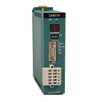
Chapter 2 Names of Parts and their Functions
2
: ON : Blink : OFF
(2) Ethernet Connectors (EN-A, EN-B)
These are Ethernet communication ports. Connect AUI cables to them in case of the
EN711 or EN721 (10BASE5) modules, coaxial cables to them in case of the EN731
or EN741 (10BASE2) modules, or twisted pair cables to them in case of the EN751,
EN751A, EN761, or FN711 (100BASE-TX, 10BASE-T) modules.
(3) Serial communication port RS-232C (TOOL)
This is the RS-232C port for tool/debugger. The connector is the 9-pin D-sub type. It
may be used for tool or debugger as selected with the 8-bit DIP switch (operation
mode setting switch) in the module.
Normally, the module is used in tool mode, not in devugger mode (Do not change the
setting).
Table 2-2 Indication of FN Status LEDs
LED
Mode
Controller Type
Description
RUN HELT Dual-line
Single-line
OFF OFF Power OFF Yes Yes Power switched off
ERROR Yes Yes Down
INZ Yes Yes Just after power is switched on.
Changes to other mode in 1 second.
RCV Yes No Equalizing by standby controller of dual-
line system. Changes to other mode after
equalizing.
HALT Yes Yes This mode is selected when HALT
command is issued by Engineering Tool.
Changes to RUN mode when RUN
command is issued by Engineering Tool.
HOLD Yes Yes Other module is halted. This mode is
selected at the same time as other
module shifts to other mode.
WAIT Yes Yes Waiting for other module to finish
initializing. Changes to other mode when
all modules are initialized.
MEM-Clear end Yes Yes Starts by specifying memory clear. This
mode is selected when memory clear is
over.
DL-WAIT Yes Yes Indicates that FN is waiting for download.
Transition by download from Engineering
Tool.
RUN Yes Yes Indicates tag processing under way.
Normal operation.
EQL Yes No Tag processing under way by the online
set of dual controller; downloading to the
standby set.
●
○
●
☆
☆
○
○
○
○
☆
●

 Loading...


