16 model 3000 Ethernet Module / DS Connection Module Operation Manual
Chapter 3 Setting
3
3.1.3 Operation mode setting switches (MODE)
The product has in it the 8-bit DIP switches that determine EN7 and FN module
operation. Use a small screwdriver for their setting.
Each of these switches for EN711, EN721, EN731, and EN741 is described in Table 3-2
Operation Mode Setting Table.
Note: This mode is valid for EN711 and EN731 only. (Not applicable to EN721 and
EN741 dual systems. If this mode is used, it is valid for line A only, provided that
a single socket interface is employed.)
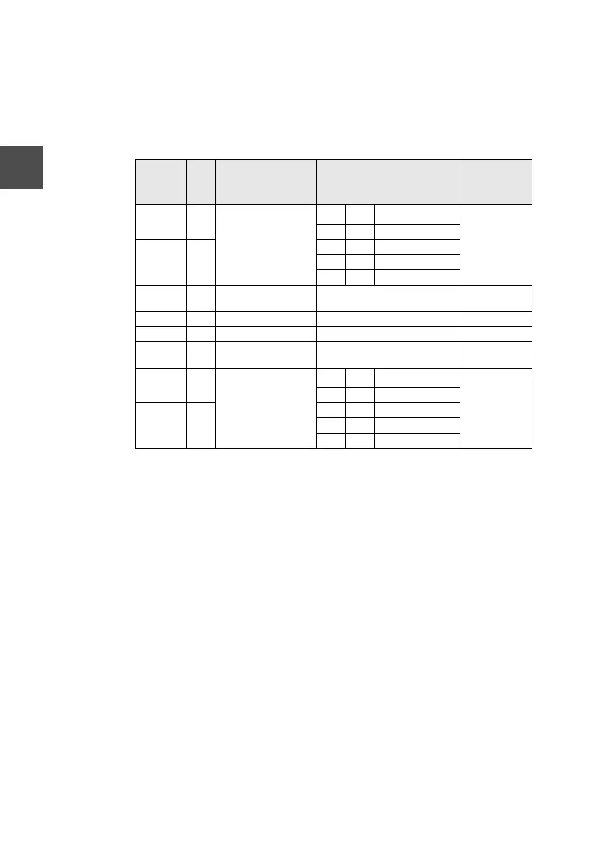
Table 3-2 Operation Mode Setting Table (EN711, EN721, EN731, EN741)
Switch No.
Name
Function Setting
Default
(Before
shipment)
1 M0 Operation mode
M1 M0 Operation
M1=off
M0=off
(Normal setting)
off off Normal
2 M1 off on Reserve
on off Download
on on Test program
3 SL RS-232C function
selection
on : Debugger, off : Tool off
4 GW Relay function (future) on : Provided, off : None off
5 S0 Spare 0 Unused off
6 IPF IP address restriction
(Note)
on : Free, off : Restricted off
7 IP0 IP address type
IP1 IP0 Operation
IP1=off
IP0=off
(Class B
setting)
off off Class B (General)
8 IP1 off on Reserve
on off TOSDIC-CIE 1200
on on Set from tool
 Loading...