66 model 3000 Ethernet Module / DS Connection Module Operation Manual
Chapter 6 Maintenance and Inspection
6
6.2 Troubleshooting
If the LEDs that indicate the status of the product show other than the normal indications
specified in Table 2-1 (page 9) in Chapter 2, or if an error is detected at a human
interface station, stop using the product and contact the nearest Toshiba service office
concerned.
For troubleshooting with the LEDs, see Table 6-1.
For how to read RAS data, system logs, etc., refer to the Operation Manual for the
Engineering Tool.
Note: The memory backup time of the Ethernet module varies depending on the ambi-
ent module temperature as follows:
EN711, EN721, EN731, EN741: 24 hours or more (at 25
o
C)
EN751A: 20 hours or more (at 25
o
C)
Because the information may become lost if power is switched off for a long time, collect
it as soon as possible using the Engineering tool or general-purpose serial
communication software (Hyper Terminal, an accessory to Windows, for example)
Remember, however, that the backed up information is RAS data, system log, etc., and
does not include control data. Therefore, operation at restart will not be adversely
affected.
The EN751, EN761, and FN711 have their RAS data and system log saved in the
memory by the battery in the power module connected to the base unit.
If an error occurs, read out the RAS data and system log before removing the modules
from the base unit.
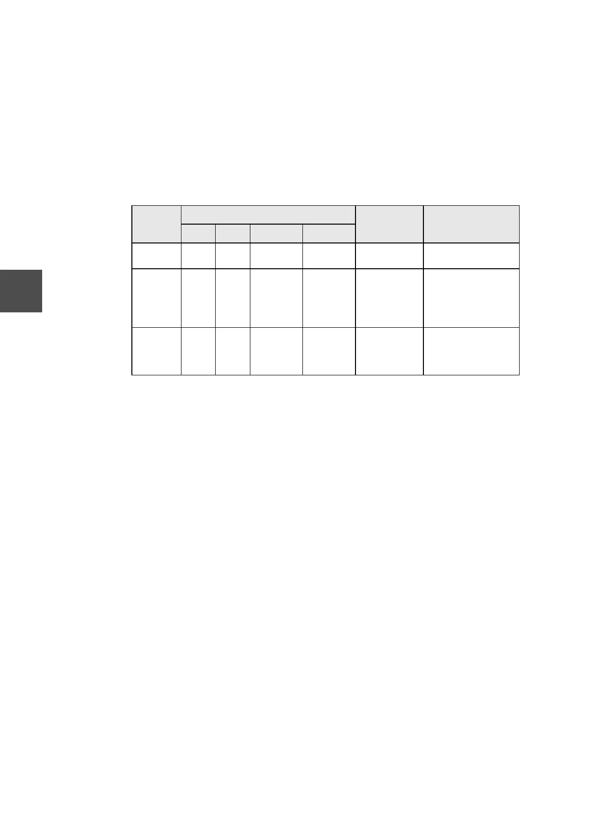
Table 6-1 Troubleshooting with LEDs Item
Item
LED indication
Status Step to be taken
RUN HLTH L-A L-B
Normal
operation
ON ON Blink or ON Blink or ON Normal –
WDT
inhibit
Blink ON Blink or ON Blink or ON Wrong setting Enable WDT with
internal jumper pin.
Contact Toshiba
service office
concerned.
Down OFF OFF – – Module faulty Replace module.
Contact Toshiba
service office
concerned.
 Loading...