F. Use of Attachments
The Handles and the Ankle Cuffs connect to the “O-Rings” at the ends of the
Resistance Bands (housed in the Power Pods - see page 11 or connect to the
Support Legs – see Leg Extender on page 11)
1. Power Pods
• Each Power Pod holds 3 Resistance Bands, varying in resistance (“weight”): Grey (low
resistance), Black (medium resistance) and Red (heavy resistance) (see 1 below).
• Each Resistance Band is fitted with an O-Ring. By clipping the Handles or Ankle
Cuff onto one or more of the O-Rings (see 1, 2 & 3 on page 11), the level of
exercise resistance can be varied - see Resistance Chart on Exercise Chart.
• When moving the Power Pod Seat (with settings: 1,2,3,4 & 5), the Power Pods
(attached to the seat) move in harmony, allowing the resistance to become
suitably aligned to the muscle(s) to be exercised.
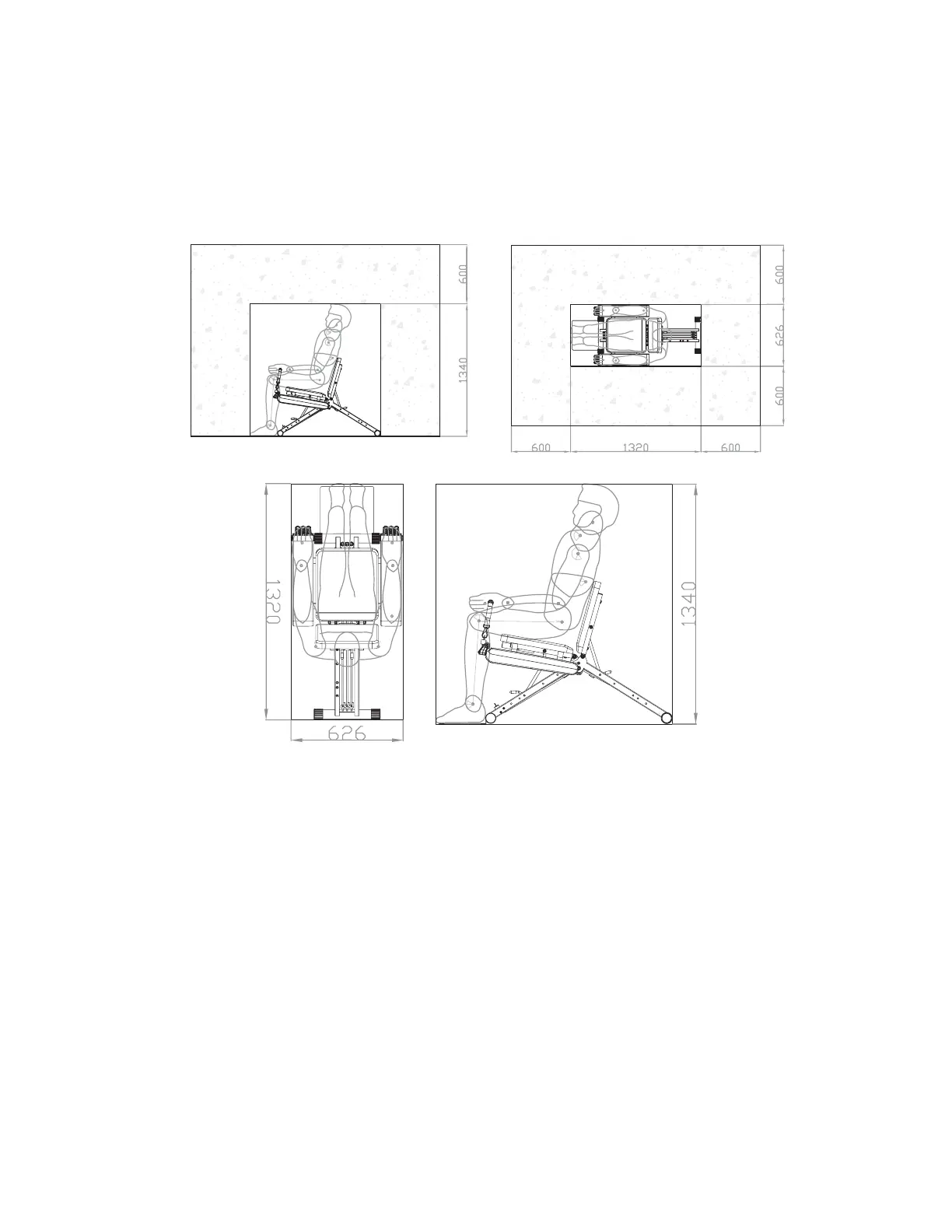
Setting Up Your Workout Area
Make sure that you have enough space around your Total Flex™ L machine. The
following diagrams demonstrate the ‘training area’ (Figure 1a & 1b) as well as the
minimal ‘free area’ (Figures 2a & 2b) that should be available around you while you
are working out on this unit.
2a 2b
MINIMUM
MINIMUM MINIMUM
MINIMUM MINIMUM
1a 1b
10