L-shaped angle
iron screw
frame
Cloud Management Switch Installation Manual
10 product installation
Therefore, please ensure that the rack grounding wire is installed correctly; ÿ
Equipments are generally installed in the rack from bottom to top to avoid overload installation; ÿ Avoid placing
other heavy objects on the surface of the switch to avoid accidents; ÿ Ensure heat dissipation and air
circulation.
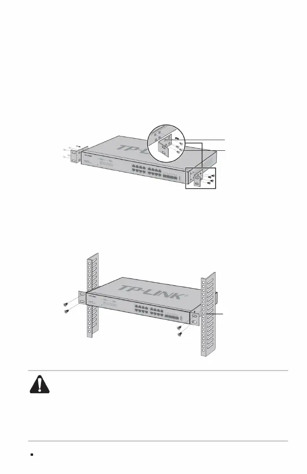
Figure 2-2 Angle iron installation diagram
3. Place the switch in an appropriate position in the rack and support it on the bracket; 4. Use screws to fix
the L-shaped angle irons to the fixed guide grooves at both ends of the rack to ensure that the switch is installed stably and horizontally on the
rack. As shown below.
Note: ÿ
Good grounding of the rack is an important guarantee for the equipment’s anti-static, anti-leakage, lightning protection and anti-interference.
1. Check the grounding and stability of the rack; 2. Install the
two L-shaped angle irons in the accessories on both sides of the switch panel, and use the accessories to
The screws provided are fixed as shown in the figure below;
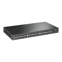
ÿ Installed on 19-inch standard rack
The TL-SE2420/TL-SE2226 switch is designed according to the size of a 19-inch standard rack
and can be easily installed on the rack. The specific installation steps are as follows:
Machine Translated by Google