User Guide 6
Introduction Appearance Description
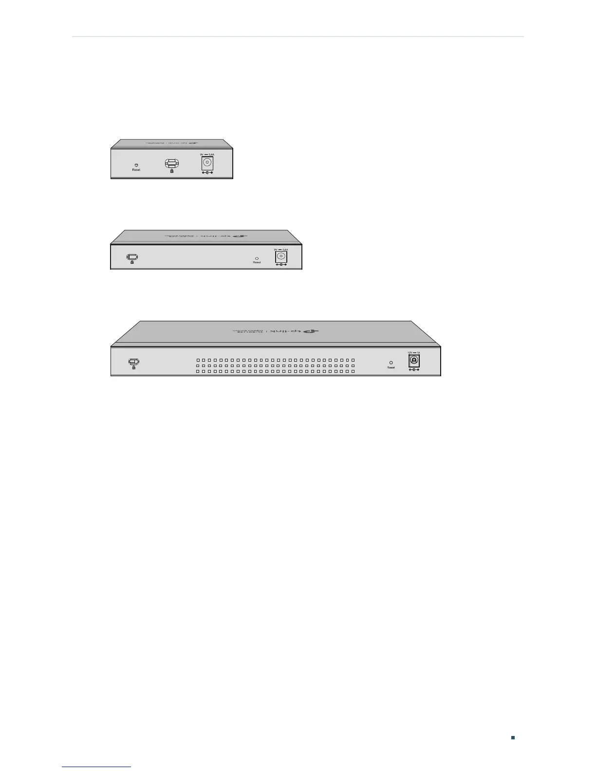
2.2 Rear Panel
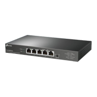
The rear panel of TL-SG105E is shown as the following figure.
Figure 2-4 Rear Panel of TL-SG105E
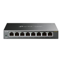
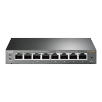
The rear panel of TL-SG108E is shown as the following figure.
Figure 2-5 Rear Panel of TL-SG108E
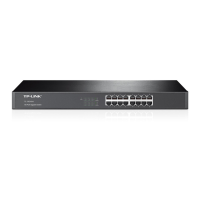
The rear panel of TL-SG116E is shown as the following figure.
Figure 2-6 Rear Panel of TL-SG116E
Kensington Security Slot
Secure the lock (not provided) into the security slot to prevent the device from being stolen.
Reset
With the switch powered on, press this button for five seconds or above to reset the
software setting back to factory default setting.
DC Power Socket
Connect the female connector of the power cord here, and the male connector to the AC
power outlet. Make sure the voltage of the power supply meets the requirement of the input
voltage (9V/0.6A for TL-SG105E and TL-SG108E, 12V/1A for TL-SG116E).