Switching Configuration Examples
User Guide
35
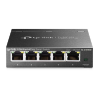
3) Choose the menu Switching > IGMP Snooping to load the following page. Enable IGMP
snooping. Click Apply.
Figure 5-4 Configuring IGMP Snooping
5.2 Example for Configuring LAG
5.2.1 Network Requirements
As shown below, hosts and servers are connected to Switch A and Switch B, and heavy
traffic is transmitted between the two switches. To achieve high speed and reliability of
data transmission, you can bundle multiple physical ports into one logical interface. In this
case, we bundle port 1, port 2 and port 3 of both switches into one logical interface.
Figure 5-5 Network Topology for LAG
Switch A Switch B
Hosts
Port 1
Port 1
Port 3
Port 3
Servers
Port 2 Port 2
Demonstrated with TL-SG105E, the following section provides configuration steps. The
configuration steps are similar for both switches, here we take Switch A for example.
5.2.2 Configuration Steps
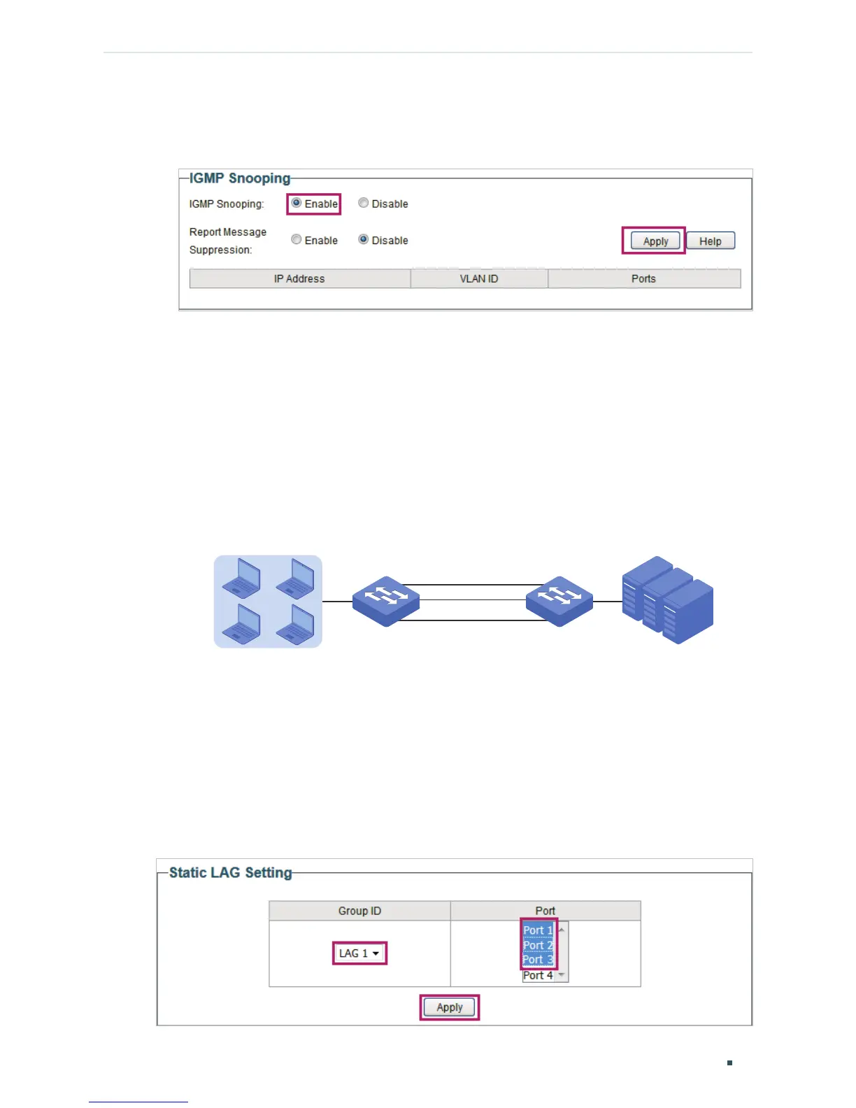
Choose the menu Switching > LAG to load the following page. Add Port 1, Port 2 and Port
3 to LAG 1. Click Apply.
Figure 5-6 Configuring LAG