TRWinProg Parameterization: CO_58 / C_H80 / C_H110
TR-Electronic GmbH 2005, All Rights Reserved Printed in the Federal Republic of Germany
Page 102 of 107 TR - ECE - BA - DGB - 0039 - 14 07/30/2020
8.2.1.6 Check sum 28 after 25-28 data bits
The selection "Check sum 28 after 25-28 data bits" causes that the
measuring system transmits its data in TR-SSI-format:
• 28 data bits in binary code (MSB bit first)
- Check sum 28 after 25 data bits:
Number of revolutions = 12 bits, Number of steps per revolutions = 13 bits,
this corresponds to a max. total measuring length of
8192 steps/revolution x 4096 revolutions. After output of the position 3
zero bits are attached, in order to keep the data frame of 28 bits.
- Check sum 28 after 26 data bits:
Number of revolutions = 12 bits, Number of steps per revolutions = 14 bits,
this corresponds to a max. total measuring length of
16384 steps/revolution x 4096 revolutions. After output of the position 2
zero bits are attached, in order to keep the data frame of 28 bits.
- Check sum 28 after 27 data bits:
Number of revolutions = 12 bits, Number of steps per revolutions = 15 bits,
this corresponds to a max. total measuring length of
32768 steps/revolution x 4096 revolutions. After output of the position 1
zero bit is attached, in order to keep the data frame of 28 bits.
- Check sum 28 after 28 data bits:
Number of revolutions = 12 bits, Number of steps per revolutions = 16 bits,
this corresponds to a max. total measuring length of
65536 steps/revolution x 4096 revolutions.
• 15 check sum bits (MSB bit first)
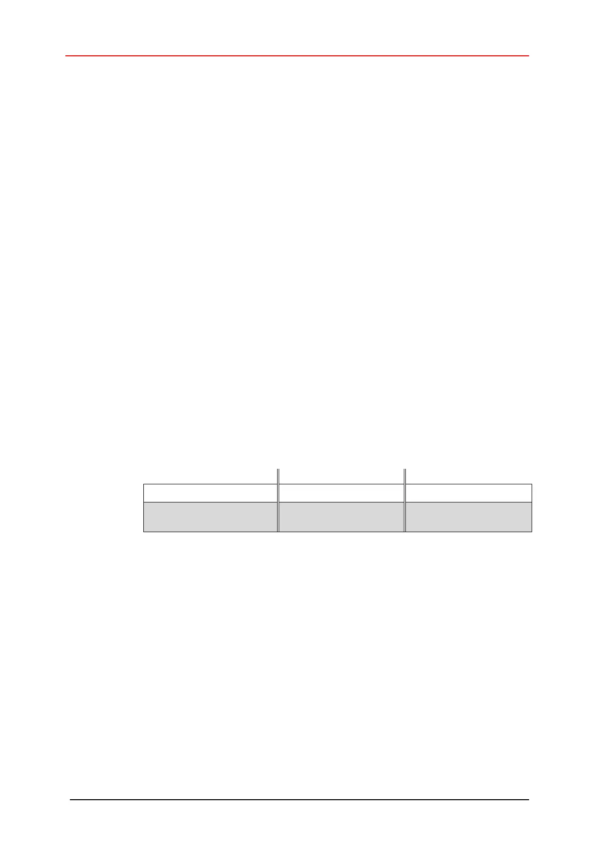
Example of the protocol structure for the selection
Check sum 28 after 28 data bits
:
MSB LSB
1 – 12 13 – 28 29 – 43
P 2
27
– P 2
16
P 2
15
– P 2
0
CRC 2
14
– CRC 2
0
12 bit
Number of revolutions
16 bit
Number of steps per revolution
15 bit
TR Check sum
The transmission format with check sum works with a "Hamming Distance" of 6 and
recognizes up to 5 errors per code word. Moreover, interrupted clock- or data-lines in
the receiver device can be recognized.
As receive devices (SSI master) serve TR application modules, e.g. the "AK-41" axis
cassette.
Because of high immunity to disturbance with this transmission format, this technology
is used e.g. in areas with strong electro smog and long connection lines.