TR-Electronic GmbH 2005, All Rights Reserved Printed in the Federal Republic of Germany
Page 36 of 43 TR - ECE - BA - DGB - 0046 - 06 08/23/2016
4 Instructions for mounting / schematic
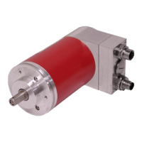
4.1 Solid shaft
The Measuring systems with solid shaft are connected to the drive shaft via an elastic
coupling, which compensates for any deviations in the axial and radial direction
between the measuring system and drive shaft. This avoids excessive strain on the
bearings.
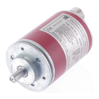
4.1.1 Flange mounting
The centering collar with the corresponding fit centers the measuring system in
relation to the shaft. It is fixed to the machine by means of three screws in the flange.
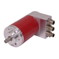
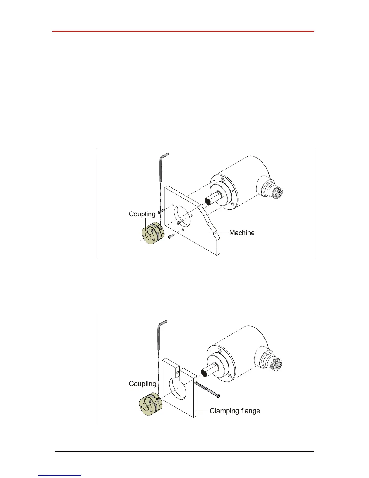
4.1.2 Clamping flange
The centering collar with the corresponding fit centers the measuring system in
relation to the shaft. It is fixed to the machine by means of the clamping flange.
 Loading...