&21752/6,1',&$7256
&RS\ULJKW7UDFH(QJLQHHULQJ&R,QF 7HOHSKRQH 3DUW1XPEHU
WK
6WUHHW1( )D[ 2FWREHU
$UOLQJWRQ:$86$ ZZZWUDFHHQJLQHHULQJFRP 3DJH
&RQWUROV,QGLFDWRUV
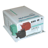
The Mariner inverter/chargers feature a two-position On/Off rocker switch, tri-color status indicator,
battery temperature sensor (BTS) port, remote control port, and a charger circuit breaker on the front
panel.
Figure 2, Controls and Indicators
1. On/Off Switch: Turns the inverter on or off.
ON: the inverter transforms 12-volt direct current from the batteries into 120-volt, 60 Hz alternating
current whenever AC current is not present at the AC Input Hot 1 terminal.
When 120-volt AC is present at the AC Input Hot 1 terminal, the inverter will pass the current through
to any AC loads connected to the inverter, and the standby battery charger will charge the batteries.
OFF: the inverter will not create AC power from the batteries, but will pass through AC current when
it is present at the AC Input Hot 1 terminal. The standby battery charger will charge the batteries
regardless of the position of the On/Off switch.
1
&$87,21
12
11
10
9
8
7
6
5
4 3
2
1

 Loading...