,167$//$7,21
&RS\ULJKW7UDFH(QJLQHHULQJ&R,QF 7HOHSKRQH 3DUW1XPEHU
WK
6WUHHW1( )D[ 2FWREHU
$UOLQJWRQ:$86$ ZZZWUDFHHQJLQHHULQJFRP
3DJH
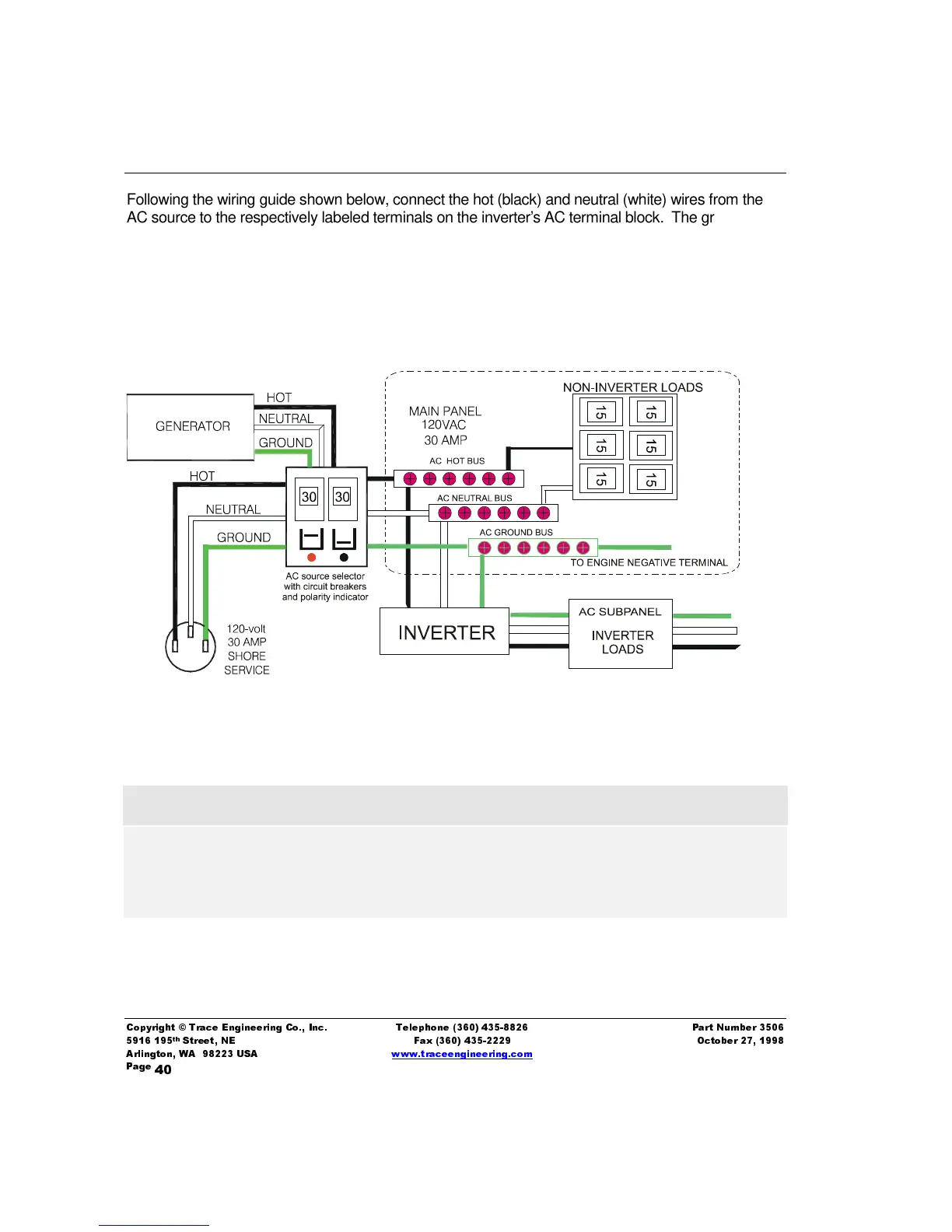
Following the wiring guide shown below, connect the hot (black) and neutral (white) wires from the
AC source to the respectively labeled terminals on the inverter’s AC terminal block. The ground
(green) should be connected to the terminal stud labeled “ground” bolted to the floor of the chassis.
Repeat the procedure for the AC wiring going to the AC sub-panel which will power the loads, except
connect these wires to the terminals labeled AC out.
3. Inspect all wiring for proper installation and then replace the cover using the two 6/32nds screws
and lock washers to secure it.
Figure 13, Typical AC Wiring Diagram
,PSRUWDQW3UHFDXWLRQ
The output side of the inverter’s AC wiring should at no time be connected to
any AC power source. This condition is far worse than a short circuit. If the
unit survives this condition, it will shut down until corrections are made.
AC output must be isolated from ground to comply with the NEC requirement for neutral-ground
switching. This is easiest to do at the sub-panel by isolating the neutral connector block from
the frame of the subpanel with an appropriate insulator.