,167$//$7,21
&RS\ULJKW7UDFH(QJLQHHULQJ&R,QF 7HOHSKRQH 3DUW1XPEHU
WK
6WUHHW1( )D[ 2FWREHU
$UOLQJWRQ:$86$ ZZZWUDFHHQJLQHHULQJFRP 3DJH
GFCI’s may be used on single-phase 120-volt AC circuits only if the system has a polarity indicator
as the AC disconnect device. Some GFCI’s will nuisance trip when used with a modified square
wave inverter. Trial is the only way to tell for sure. On the above listed types, continued nuisance
tripping is usually a result of a wiring problem in the inverter AC output system. Leakage currents
present somewhere in the AC system are causing the GFCI to trip. Make a careful review of the AC
wiring layout in your system and look for possible unwanted ground paths. An error in wiring of the
neutral-ground switching system is a good place to start troubleshooting. Be sure that the AC output
neutral is isolated from the ground. A multimeter may be handy in this troubleshooting procedure.
Neutral-to-Ground Switching
All of the Mariner Series units employ neutral-to-ground switching as required by the NEC (National
Electric Code). The purpose for this requirement is to ensure that the neutral conductor in a three-
wire system is "bonded" or connected to ground at only one point. This prevents a voltage
difference from developing between the shorepower neutral and the vessel' neutral, which may
cause an electric shock. When the unit is operating as an inverter, the AC output neutral is
connected to the chassis ground by an internal relay, creating the bond within the inverter. When
operating from an external AC power source the internal relay in the inverter opens and removes the
ground from the neutral conductor and allows the "bond" to be provided by the external AC source.
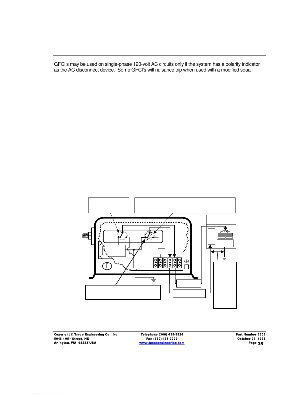
The diagram on the below graphically describes the ground switching system in the inverter for a unit
operating as an inverter and feeding the AC sub-panel.
Figure 9, Neutral-to-Ground Switching without external AC source
RY-A
RY-B
HOT OUT
The
neutral
conductor
shall be
insulated
from the
equipment
grounding
conductors
or
enclosures
NEUTRAL OUT
Neutral-to-Ground “BOND” is provided by the
internal relay for entire AC system
AC Sub-panel
Inverter loads
N
E
U
Inverter
AC
out
GND
Relay RY-A connects the
inverter out to the AC
HOT output.
Relay RY-B connects the NEUTRAL (OUT) to chassis or vehicle
ground when AC power is not present at the inverter input. This
assures all equipment in the vehicle is referenced to the same ground.