48,&.,167$//
&RS\ULJKW7UDFH(QJLQHHULQJ&R,QF 7HOHSKRQH 3DUW1XPEHU
WK
6WUHHW1( )D[ 2FWREHU
$UOLQJWRQ:$86$ ZZZWUDFHHQJLQHHULQJFRP
3DJH
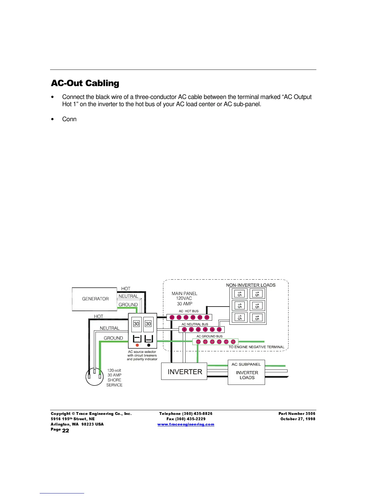
$&2X W&DEOLQJ
•
Connect the black wire of a three-conductor AC cable between the terminal marked “AC Output
Hot 1” on the inverter to the hot bus of your AC load center or AC sub-panel.
•
Connect the white wire from the terminal marked “AC Output Neutral” to the neutral bus of your
AC load center or sub-panel.
•
Connect the remaining green wire bolted to the chassis of the inverter to the safety ground bus of
the AC load center or sub-panel. Install the AC terminal cover with the screws provided.
:UDSXS
•
Secure all cables with wire ties or other non-conductive fasteners to prevent chafing or damage
from movement and vibration. Use strain relief’s, grommets, or conduit to prevent damage to the
wiring where it passes through bulkheads or any apertures. Tighten all connections to 10-15 foot
pounds. Install the red, green, and black inverter battery terminal covers.
•
Affix the "Warning…Vessel is equipped with a DC to AC power inverter…" decal to the AC load
center or sub-panel powered by the inverter.
•
Check to see that the inverter front panel switch is in the “Off” position, then reconnect to the AC
power source.
•
Turn the inverter to the “On” position and check inverter operation (See
Operation
section).
Figure 4, Typical AC Wiring Diagram