,167$//$7,21
&RS\ULJKW7UDFH(QJLQHHULQJ&R,QF 7HOHSKRQH 3DUW1XPEHU
WK
6WUHHW1( )D[ 2FWREHU
$UOLQJWRQ:$86$ ZZZWUDFHHQJLQHHULQJFRP
3DJH
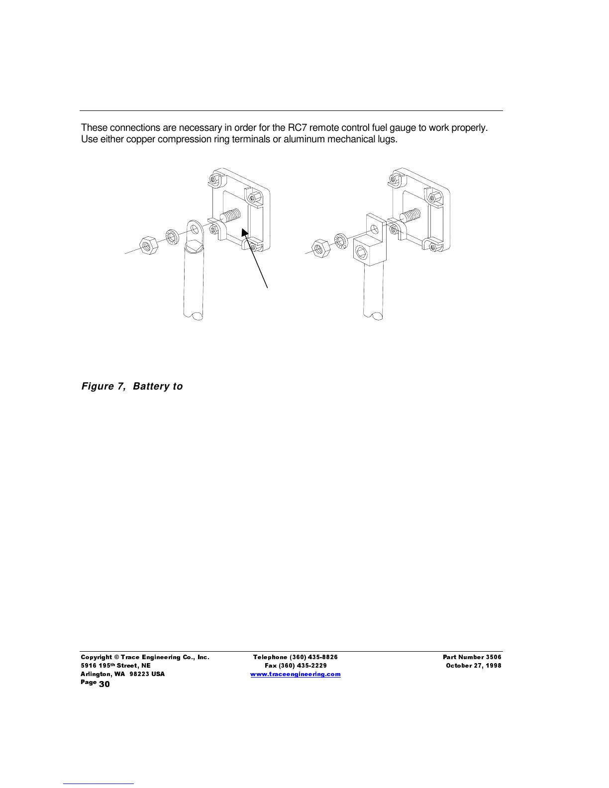
These connections are necessary in order for the RC7 remote control fuel gauge to work properly.
Use either copper compression ring terminals or aluminum mechanical lugs.
Figure 7, Battery to Inverter Cable Connection
Copper Compression Lugs: Commonly available at hardware, welding, and auto parts retailers,
compression lugs must be crimped onto each cable using an appropriate crimping tool. These lugs
are not available from Trace Engineering. Suggested sources and part numbers are:
Hollingsworth, Pompano Beach, FL 305-979-2050
Part # Description
TL3061 2/0 Ring Terminal
TL3062 4/0 Ring Terminal
H40 8 AWG to 250MCM Air-Operated Crimping Tool
Thomas & Betts
K973 2/0 Ring Terminal
M973 4/0 Ring Terminal
RJ737 2/0 Insulated Ring Terminal
RL737 4/0 Insulated Ring Terminal
TBM6 Hand Operated Crimping Tool (order dies separately)
Dies: #11809 for crimping 2/0 non-insulated lugs
#11811 4/0 non-insulated lugs
#11826 2/0 insulated lugs
#11828 4/0 insulated lugs
2/0 Copper Compression Lug
2/0 Aluminum Mechanical Lug
Do not place anything between
battery cable lug and terminal
surface. Assemble exactly as shown