,167$//$7,21
&RS\ULJKW7UDFH(QJLQHHULQJ&R,QF 7HOHSKRQH 3DUW1XPEHU
WK
6WUHHW1( )D[ 2FWREHU
$UOLQJWRQ:$86$ ZZZWUDFHHQJLQHHULQJFRP 3DJH
Installation Procedure
1. Disconnect the inverter from the battery bank (if already connected), by either removing the DC
fuse or opening the DC disconnect. Disconnect the shorepower conductor. Disable the
automatic generator start device (if so equipped). Check to see if any AC or DC power is
present (use a multimeter if necessary).
2. Determine which knockout(s) will be utilized and remove them from the inverter. Install strain
relief in the inverter knockout holes. These require a 1" strain relief available at hardware stores
or building supply centers. Using appropriate conduit connectors (if using conduit), fasten the
conduit to the inverter. Feed all AC wiring through the conduit and into the inverter AC terminal
block (located on the front of the inverter). Be sure to leave yourself extra wire to work with. You
need at least two sets of three conductor wiring, one for AC Hot, neutral, and ground into the
inverter, and another for AC hot, neutral and ground out of the inverter to the loads. Torque all
AC terminals to 10 to 15 inch-pounds.
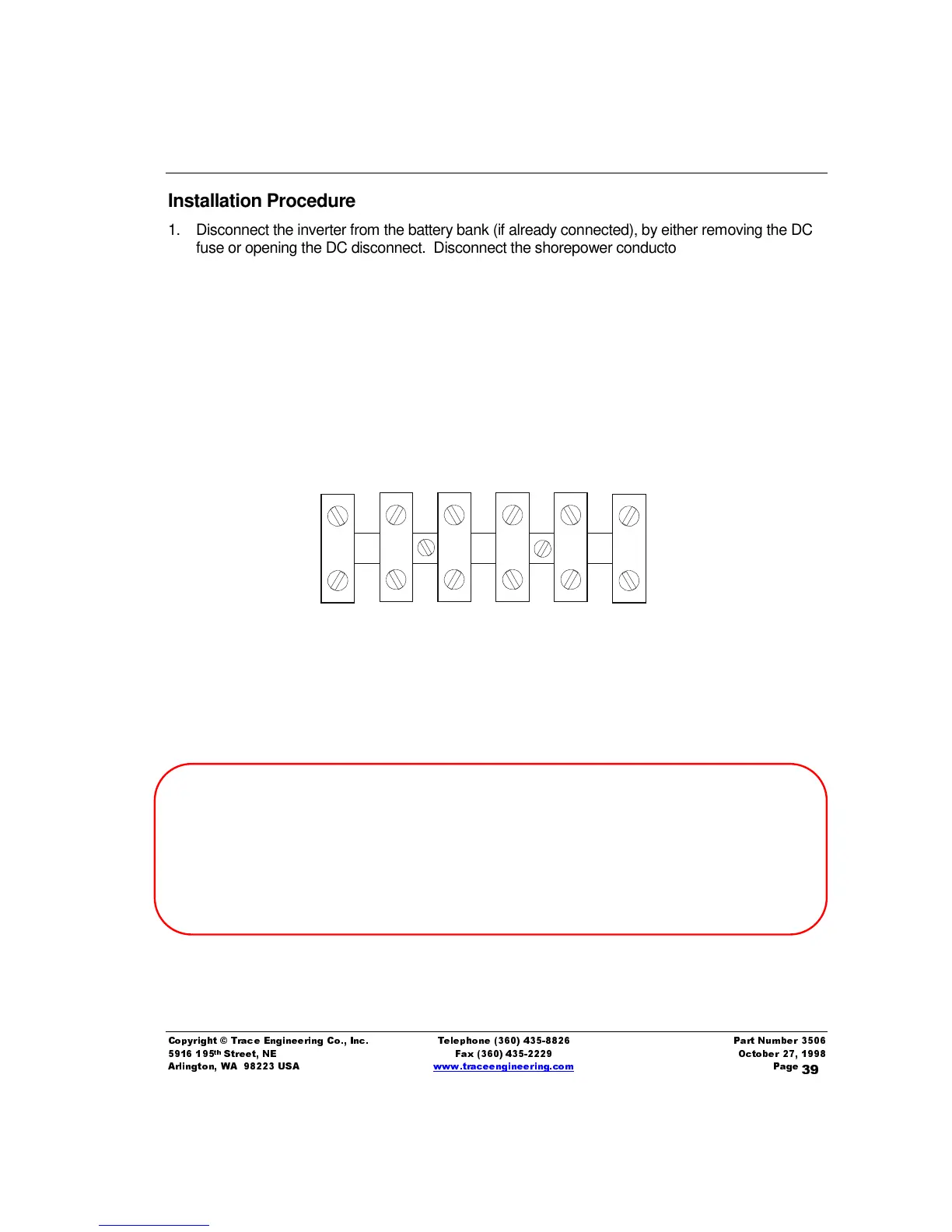
Figure 12, AC Terminal Block
ABYC E-8.15
All connections normally carrying current shall be made in enclosures to protect against shock hazards. Unused
openings in boxes, cabinets and enclosures shall be closed. Current-carrying conductors shall be routed as high as
practicable above the bilge water level and other areas where water may accumulate.
Conductors which may be exposed to physical damage shall be protected by self-draining loom, conduit, tape,
raceways or other equivalent protection. Conductors passing through bulkheads or structural members shall be
protected to minimize insulation damage such as chafing. Conductors shall also be routed clear of sources of chafing
such as steering cable and linkages, engine shafts and control connections. Twist-on connectors (wire nuts) shall not
be used. No more than four conductors shall be secured to any one terminal stud.
AC INPUT
NEUTRAL
AC INPUT
HOT 1
AC OUTPUT
NEUTRAL
AC OUTPUT
HOT 1