,167$//$7,21
&RS\ULJKW7UDFH(QJLQHHULQJ&R,QF 7HOHSKRQH 3DUW1XPEHU
WK
6WUHHW1( )D[ 2FWREHU
$UOLQJWRQ:$86$ ZZZWUDFHHQJLQHHULQJFRP 3DJH
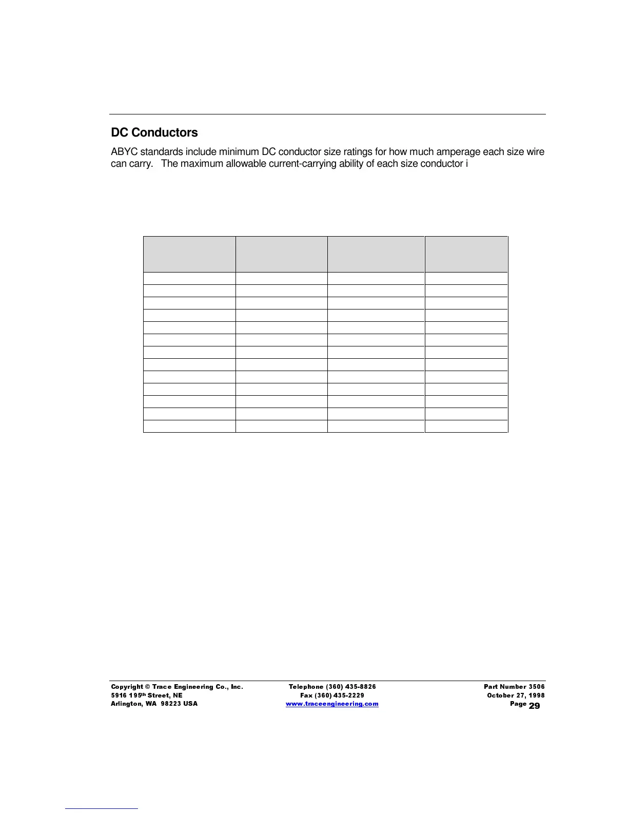
DC Conductors
ABYC standards include minimum DC conductor size ratings for how much amperage each size wire
can carry. The maximum allowable current-carrying ability of each size conductor is listed in the
following table.
Table 6, Maximum Amperage for Conductors Under 50 Volts at 105ºC
AWG Wire Size Metric Wire Size
Amperage
Outside Engine
Spaces
Amperage in
Engine Spaces
18 .8 20 17
16 1 25 21.3
14 2 35 29.8
12 3 45 38.3
10 5 60 51
8 8 80 68
6 13 120 102
4 19 160 136
2 32 210 18.5
0 50 285 242.3
00 62 330 280.5
000 81 385 327.3
0000 103 445 378.3
DC Cabling Connections
Color-code your battery cables with colored tape or heat shrink tubing. The standard is red for
positive (+) and black for negative (-).
Cables must have soldered and crimped, or crimped copper compression lugs unless aluminum
mechanical lugs are used. Soldered connections alone are not acceptable. We suggest using high
quality, UL-listed Trace Engineering battery cables. These cables are available in a specific
assortment of sizes from 1 ½ to 10 feet, and in 2/0 or 4/0 AWG. They are color-coded and have
pressure crimped, sealed ring terminals. Contact your Trace dealer to order.
Figure 7, Battery to Inverter Cable Connection
illustrates proper connections for the Mariner
inverter/chargers. Points of caution are:
ä Do not connect the battery negative (-) cable to the vessel safety ground; connect it to the
battery negative terminal of the inverter.
ä Do not connect equipment DC negatives to the safety ground, connect only to the negative
bus of the DC load center.