,167$//$7,21
&RS\ULJKW7UDFH(QJLQHHULQJ&R,QF 7HOHSKRQH 3DUW1XPEHU
WK
6WUHHW1( )D[ 2FWREHU
$UOLQJWRQ:$86$ ZZZWUDFHHQJLQHHULQJFRP 3DJH
If no neutral to ground switching were employed in an inverter there would be one neutral tied to the
AC sub-panel and the other neutral to the vessel’s ground. The two different ground points would
now form a current carrying conductor with the vessel’s grounding conductor (’green wire’) acting as
the “wire” between the two different ground points. This means any ground point in the vessel
becomes a potential current carrying conductor, which could result in electrical shock. This ground
loop could also be a cause for nuisance tripping of any GFCI’s (Ground Fault Circuit Interrupter).
Disabling Neutral Ground Switching
Mariner inverters employ neutral-to-ground switching. In some countries, this may not be used. In
Canada, this feature must be disabled before installation. Check local code if you are not sure
whether you must disable the neutral ground switching feature.
Note: Connect the chassis ground to the vehicle chassis even if ground switching has been disabled.
Disabling the ground switching is very simple if precautions are taken and these steps followed:
1. If the inverter is already installed, disconnect any AC sources (If any are present)
2. Disconnect the battery(s) from the inverter.
3. Remove the AC terminal block cover on the front of the inverter.
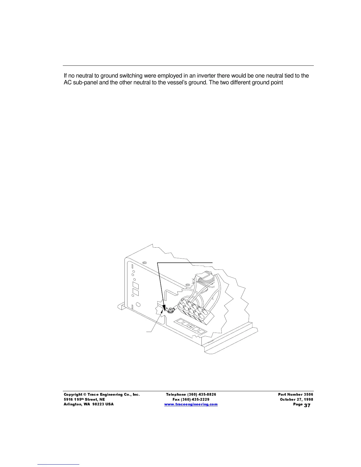
4. Locate the green wire that runs from the circuit board to the chassis ground bolt as shown
in the figure below. Disconnect this wire and wrap the terminal end with insulating tape.
Figure 11, Disabling Neutral-to-Ground Switching
Chassis ground bolt
Disconnect the gree
wire here (Neutral to
Ground Wire only)