115
2. Select the DC Volts position on the tester and
observe the meter readings for each switch positions.
NOTE: If the meter does not show voltages accord-
ing to the chart, make sure the front drive actuator is
plugged in; then troubleshoot the switches, ignition
fuses, battery connections, or wiring harness.
Fan Motor
NOTE: Preliminary checks may be performed on
this component using the diagnostic mode on the LCD
gauge (see Gauge Diagnostic Menu in this section).
NOTE: To determine if the fan motor is good, con-
nect the blue wire from the fan connector to the posi-
tive side of a 12-volt battery; then connect the black
wire from the fan connector to the negative side. The
fan should operate.
MOD474
NOTE: Fan motor resistance checks are not recom-
mended. Resistance values change with the motor
commutator position.
Lights
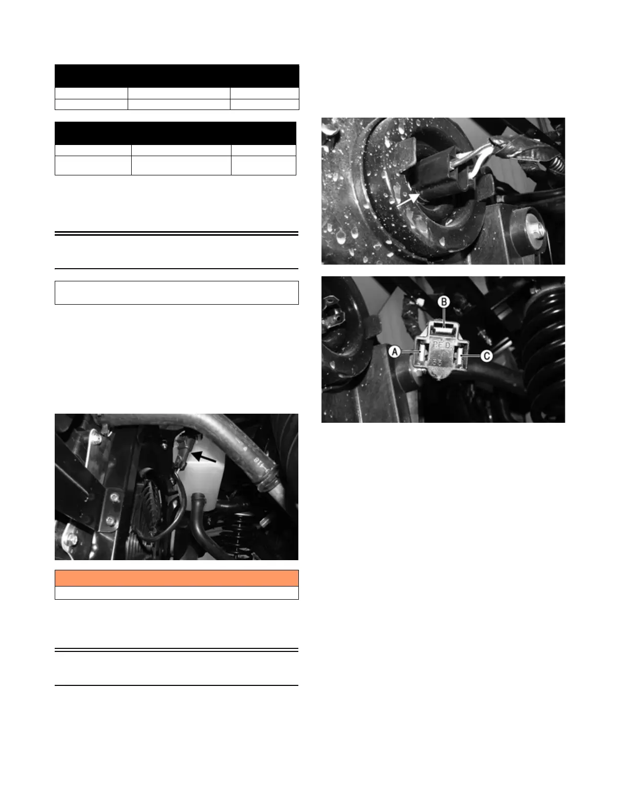
HEADLIGHTS
Voltage
Each headlight has one HI/LO three-pin connector.
NOTE: The HI/LO bulb-connector uses a three-pin
connector with the corresponding color codes: white,
yellow/black, and black.
1. Behind the headlight remove the connector from the
headlight; then set the meter selector to the DC Volt-
age position.
MOD498
MOD497
2. Connect the black meter lead to the black wire (C);
then connect the red meter lead to the white wire (B);
then turn the key switch to the ON position and turn
the light switch to LO-BEAM. Voltage must be pres-
ent. If no voltage is present, troubleshoot the LO-
BEAM fuse, or lights switch.
3. Connect the black meter lead to the black wire (C);
then the red meter lead to the yellow/black wire (A);
then turn the key switch to the on position and turn
the light switch to HI-BEAM. Voltage must be pres-
ent. If no voltage is present, troubleshoot the HI-
BEAM fuse, or lights switch.
NOTE: If both HI-BEAM and LO-BEAM have no
voltage check the lights relay, main fuse, lights switch,
battery connections, or wiring harness.
Resistance
1. Remove the plug from the center of the light switch;
then remove the screw underneath where the plug
was; then remove the nut securing the light switch to
the dash; then remove the switch assembly from the
backside of the dash; then disconnect the harness
from the switch.
2WD/4WD Switch
WIRE COLOR 2WD 4WD
Red to Orange/Gray 12.0 DC Volts 12.0 DC Volts
Red to White/Green 11.5 DC Volts 0 DC Volts
REAR LOCK/UNLOCK Switch
WIRE COLOR UNLOCK LOCK
Red to Orange/Gray 12.0 DC Volts 12.0 DC Volts
Red to Yellow/
Orange
11.5 DC Volts 0 DC Volts
Component data can be retrieved using the Dealer Diag-
nostic System. Utilize the Sensor Data screen.
! WARNING
Care should be taken to keep clear of the fan blades.