148
MOD350
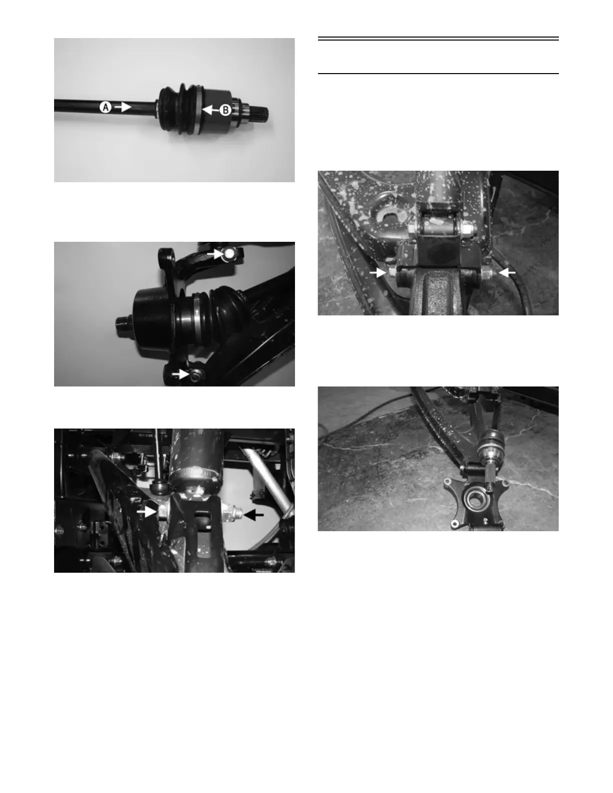
6. Install the knuckle assemblies onto the axles and ball
joints; then secure with two cap screws per side tak-
ing care not to damage the threads when installing.
Tighten to 45 ft-lb (61.2 N-m).
MOD325
7. Secure the lower shock eyelets with cap screws and
new lock nuts. Tighten to 45 ft-lb (61.2 N-m).
MOD334
8. Apply a light coat of multi-purpose grease to the hub
splines; then install the hubs (see Hub/Brake Disc in
this section).
9. Install the wheels and using a crisscross pattern,
tighten the wheel nuts in 20 ft-lb (27.2 N-m) incre-
ments to a final torque of 100 ft-lb (136 N-m).
10. Remove the vehicle from the support stand.
Drive Axles
REMOVING REAR DRIVE AXLE
1. Remove the hubs (see Hub/Brake Disc in this sec-
tion).
2. Remove the cap screw and lock nut securing the
knuckle to the upper A-arm. Discard lock nut.
Inspect cap screw and replace if damaged.
MOD367
3. While holding the drive axle stationary, use a rubber
mallet, and tap the end of the axle free from the
knuckle assembly; then pull the top of the knuckle
out and down until it is free of the drive axle; then
repeat for the other side.
MOD368
NOTE: The axle shaft must be pushed into the inner
CV joint straight.
4. Push the axle shaft (A) toward the inner CV joint
housing (B) to release the “plunge” coupler; then
while the axle shaft and the inner CV joint housing
are pushed together remove the axle from the differ-
ential; then account for the O-ring. Repeat for the
opposite side.