182
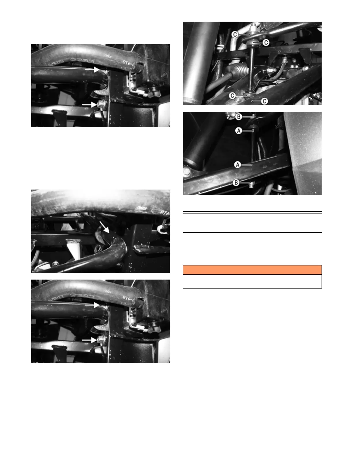
3. Remove the two cap screws per side securing the
sway bar to the frame; then remove sway bar from
frame.
MOD505
INSTALLING
1. Position the sway bar into the vehicle; then push the
sway bar mount toward the center of the vehicle and
lightly coat with grease on the sway bar where the
sway bar mount will be; then position the sway bar
mount to the mounting location and install the two
cap screws securing the sway bar to the frame. Tighten
to 20 ft-lb (27.2 N-m). Repeat for other side.
MOD506
MOD505
2. Position the sway bar link into the upper A-arms
with the four bushings as shown; then using a
wrench on the flat spot (A) of the sway bar link,
install new sway bar link lock nuts (B). Tighten so
there are 1-2 threads exposed on the upper sway bar
link and 5-6 threads exposed on the lower sway bar
link. Repeat for other side.
MOD504
MOD503
3. Remove the vehicle from the secure support stand.
Rear A-Arms
REMOVING
1. With the vehicle in Park, secure the vehicle on a sup-
port stand to elevate the wheels.
2. Remove the wheel; then remove the brake caliper;
then remove the hub.
3. Remove the lower shock cap screw and lock nut;
then secure the shock up and out the way with a suit-
able strap.
4. Remove the knuckle cap screws and lock nuts; then
remove the knuckle; then position the half shaft
away from the A-arms.
5. Remove the nylon strap and clamp securing the
brake line underneath the upper A-arm; then remove
the upper A-arm cap screws and lock nuts; then
remove the upper A-arm. Discard lock nuts. Inspect
cap screws and replace if damaged.
! WARNING
Make sure the vehicle is solidly supported on the sup-
port stand to avoid injury.