181
MOD130
7. Install the tie rod end and secure with the nut (coated
with red Loctite #271). Tighten to 32 ft-lb (43.5 N-m);
then install a new cotter pin and spread the pin to
secure the nut.
NOTE: During assembly, new cotter pins should be
installed.
MOD129
8. Apply grease to the hub and drive axle splines; then
install the hub (see Drive and Brake Systems sec-
tion).
MOD328
9. Secure the brake caliper holder to the knuckle with
two new “patch-lock” cap screws. Tighten to 45 ft-lb
(61.2 N-m).
MOD130A
10. Install the wheels and using a crisscross pattern,
tighten the wheel nuts in 20 ft-lb (27.2 N-m) incre-
ments to a final torque of 100 ft-lb (136 N-m).
11. Remove the vehicle from the support stand.
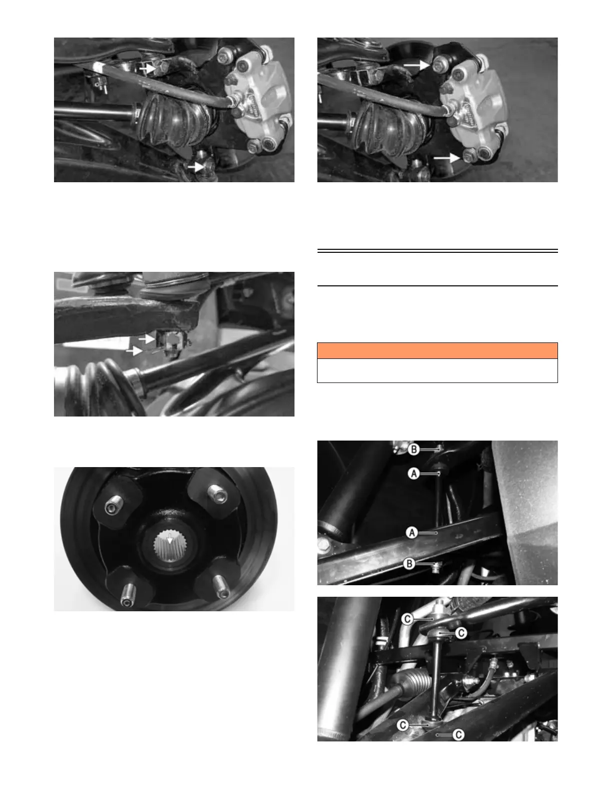
Sway Bar
REMOVING
1. With the vehicle in Park, secure the vehicle on a sup-
port stand to elevate the wheels.
2. Using a wrench on the flat spot (A) of the sway bar
link, remove at least one sway bar link lock nut (B)
per side. Account for the four sway bar link bushings
(C). Discard lock nuts.
MOD503
MOD504
! WARNING
Make sure the vehicle is solidly supported on the sup-
port stand to avoid injury.