60
Engine
This section has been organized into sub-sections which
show a progression for the complete servicing of the
engine.
NOTE: Photographs are used for clarification pur-
poses only and may not depict exact situation.
To service the crankshaft, the engine must be removed
from the frame. To service top-side, left-side, and right-
side components, the engine does not have to be removed
from the frame.
NOTE: It is recommended to use new gaskets, lock
nuts, and seals, and lubricate all internal components
when servicing the engine.
NOTE: A new ROV and an overhauled ROV engine
require a “break-in” period. The first 50 hours are
most critical to the life of this ROV. Proper operation
during this break-in period will help ensure maxi-
mum life and performance from the ROV. Instruct
the customer to follow the proper break-in procedure
as described in the Operators Manual.
SPECIAL TOOLS
A number of special tools must be available to the techni-
cian when performing service procedures in this section.
Refer to the current Special Tools Catalog for the appro-
priate tool description.
NOTE: When indicated for use, each special tool
will be identified by its specific name, as shown in the
chart below, and capitalized.
NOTE: Special tools are available from the Service
Department.
Removing Engine
Many service procedures can be performed without
removing the engine from the frame. Closely observe the
note introducing each sub-section for this important
information.
Support the vehicle on a suitable lift or jack stands allow-
ing room to perform work from the underside.
1. Remove the cargo box; then remove both the rear
inner fenders.
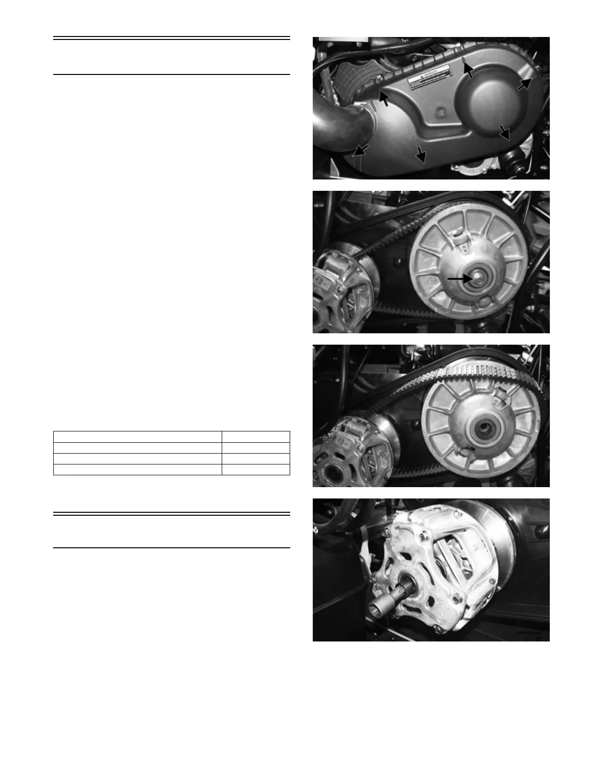
2. Remove the clutch cover; then remove the driven
clutch, drive belt, and drive clutch (see Servicing
Left-Side Components in this section).
MOD533
MOD213
MOD215
MOD390
Description p/n
Drive Clutch Puller 0744-080
Drive and Driven Holder Tool 0444-317
Valve Adjust Tool 0443-308