183
MOD371
MOD370
NOTE: When removing a lower A-arm it is
required to lift the opposite lower A-arm in order to
have access to the cap screws. This is best accom-
plished by removing the lower shock mount cap screw
for the opposite A-arm and using a suitable strap to
lift the A-arms.
MOD369
6. Remove the lower A-arm cap screws and lock nuts;
then remove the lower A-arm. Discard lock nuts.
Inspect cap screws and replace if damaged.
MOD372
CLEANING AND INSPECTING
1. Clean all A-arm components in parts-cleaning sol-
vent.
2. Inspect the A-arm for bends, cracks, and worn bush-
ings.
3. Inspect the frame mounts for signs of damage, wear,
or weldment damage.
INSTALLING
1. Install the A-arm assemblies into the frame mounts
and secure with the cap screws and new lock nuts.
Finger tighten only at this point.
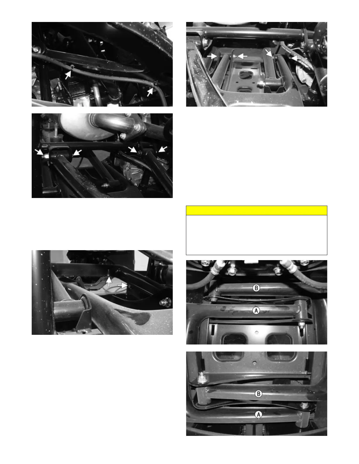
MOD507
MOD508
CAUTION
The lower rear A-arm bolts must be installed with the
driver-side A-arm (A) cap screw threads toward the rear
of the vehicle and the passenger-side A-arm (B) cap
screw threads toward the front of the vehicle as shown.
Failure to do so will result in suspension component
damage.