87
MOD458
3. Align the match marks (X) and install the clutch
cover and secure with six cap screws. Tighten using
a crisscross pattern to 110 in-lb (12.4 N-m).
WC653A
DRIVEN CLUTCH
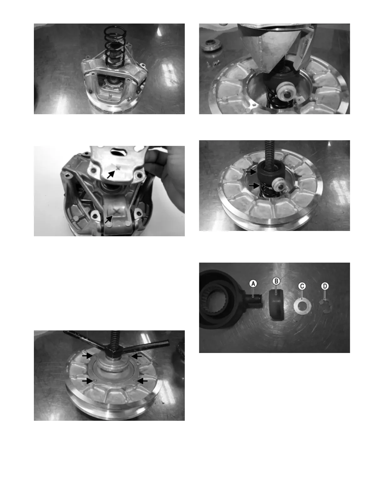
Disassembling
NOTE: Note the timing marks (X) on the cam, mov-
able sheave, and stationary sheave. These must be
aligned when assembling the driven clutch for bal-
ance purposes.
1. Using a suitable compressor, put a light amount of
pressure compressing the driven clutch; then mark
the cam and driven clutch; then remove the four cap
screws securing the cam to the driven clutch.
MOD459
2. Gently release the suitable compressor; then remove
the cam from the driven clutch assembly.
MOD460
3. Remove the spider and driven spring from the driven
clutch assembly.
MOD461
4. Remove the E-clips (D) on the end of both the spider
arms (A); then remove the rollers (B) and washers
(C) from both spider arms.
MOD465
5. Using a suitable diameter punch, drive the roll pin
securing the roller pin to the driven clutch; then gen-
tly remove the roller pin. Repeat for the other side.