13
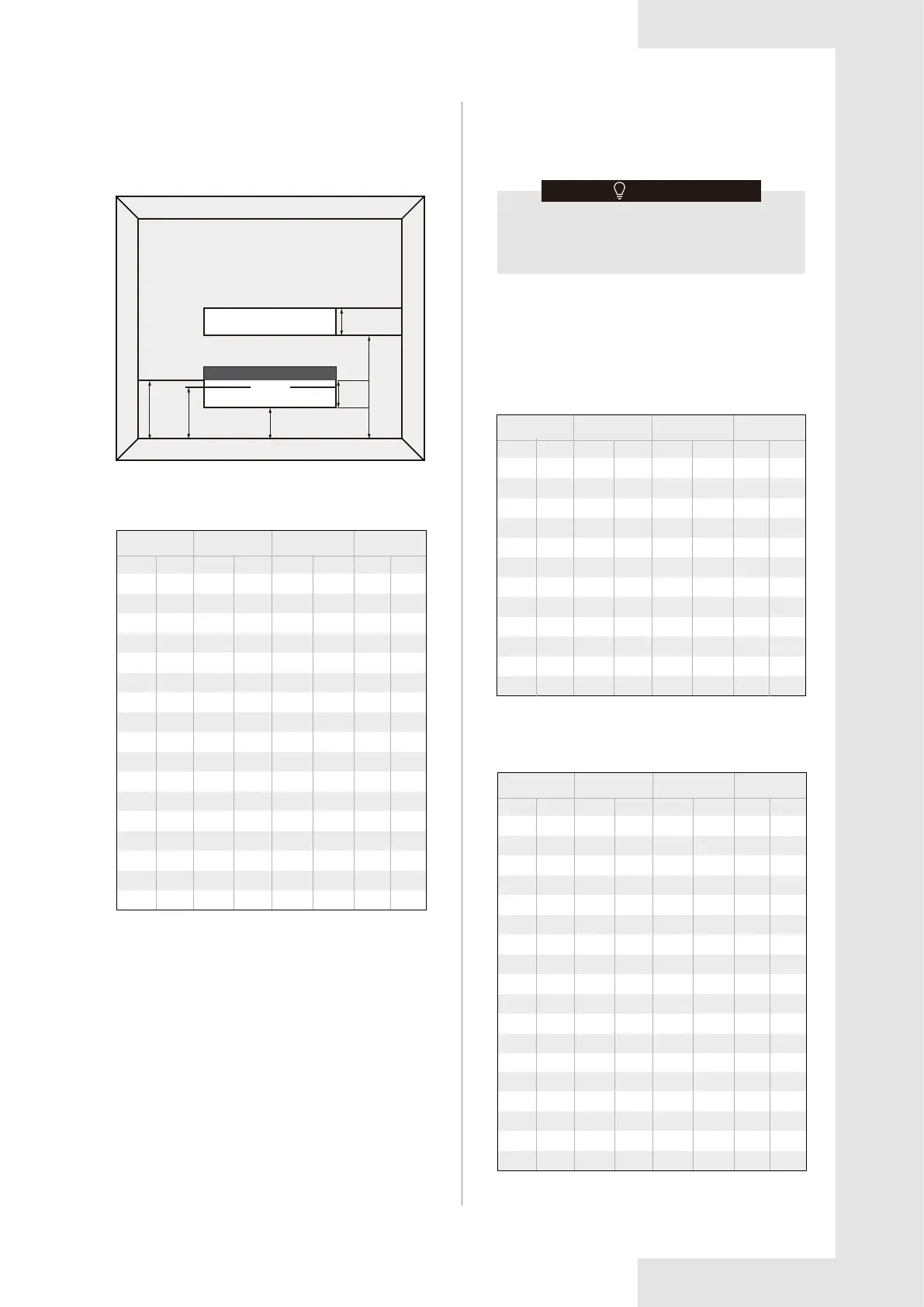
Fig. 3-3 Opening Conditions for Connected Rooms
The minimum opening for natural ventilation (Anvmin) in
connected rooms is related to the room area (A), the
actual refrigerant charge of refrigerant in the
system (Mc),
and the allowable MAXIMUM REFRIGERANT
CHARGE in
the system (Mmax), Anvmin can be determined
according to Table 3-1.
≥ 50
%
of Anvmin
≥25/32''
≥25/32''
≥59''
≤11-13/16''
≤3-15/16''≤7-7/8''
Anvmin
≥ 50
%
of Anvmin
Table 3-1
The minimum opening area for connected rooms
AnvminA
100
110
120
130
140
150
160
170
180
190
200
210
220
230
240
250
260
17-3
17-3
17-3
17-3
17-3
17-3
17-3
17-3
17-3
17-3
17-3
17-3
17-3
17-3
17-3
17-3
17-3
6-10
7-5
8-0
8-10
9-5
10-0
10-10
11-5
12-0
12-10
13-5
14-0
14-10
15-5
16-0
16-10
17-5
1.3
1.2
1.1
1.0
1.0
0.9
0.8
0.7
0.6
0.5
0.5
0.4
0.3
0.2
0.1
0.1
0.0
Mc Mmax
For appliances serving one or more rooms with an air
duct system, the room area calculation shall be
determined based on the total area of the conditioned
space (TA) connected by ducts taking into consideration
that the circulating airflow distributed to all the rooms by
the appliance integral indoor fan will mix and dilute the
leaking refrigerant before entering any room.
Note: Take the Mc=17 lb 3 oz as an example.
lb-oz
lb-oz
Table 3-2
3.5.2. The allowed maximum refrigerant
charge and required minimum room
area
If the fan incorporated to an appliance is continuously
operated or operation is initiated by a REFRIGERANT
DETECTION SYSTEM with a sufficient CIRCULATION
AIRFLOW rate, the allowable maximum refrigerant
charge (Mmax) and the required minimum room area
(Amin/TAmin) is shown in Table 3-2 and Table 3-3.
The allowable maximum refrigerant charge
Table 3-3
The required minimum room area
ft
2
m
2
ft
2
m
2
11
12
13
14
16
17
18
19
20
21
22
23
24
26
27
28
29
kg
7.8
7.8
7.8
7.8
7.8
7.8
7.8
7.8
7.8
7.8
7.8
7.8
7.8
7.8
7.8
7.8
7.8
kg
3.0
3.3
3.6
3.9
4.2
4.5
4.8
5.1
5.4
5.7
6.0
6.4
6.6
6.9
7.3
7.5
7.9
0.14
0.13
0.12
0.11
0.11
0.10
0.09
0.08
0.07
0.06
0.06
0.04
0.03
0.02
0.01
0.01
0.00
MmaxA/TA
Mmax M/TA
lb-oz
ft
2
m
2
kg
30
40
50
60
70
80
90
100
110
120
130
140
2-0
2-10
3-5
4-0
4-10
5-5
6-0
6-10
7-5
8-0
8-10
9-5
150
160
170
180
190
200
210
220
230
240
250
260
10-0
10-10
11-5
12-0
12-10
13-5
14-0
14-10
15-5
16-0
16-10
17-5
3
4
6
7
8
9
10
11
12
13
14
16
17
18
19
20
21
22
23
24
26
27
28
29
1.8
2.6
3.3
4.0
4.6
5.3
6.0
6.6
7.3
8.0
8.6
9.3
10.0
10.6
11.3
12.0
12.6
13.3
14.0
14.6
15.3
16.0
16.6
17.3
lb-oz
ft
2
m
2
kg
Mc
Amin/TAmin
lb-oz kg
ft
2
m
2
Mc
Amin/TAmin
lb-oz kg
ft
2
m
2
2-2
2-9
3-0
3-7
3-15
4-6
4-13
5-4
5-11
6-2
6-9
7-0
7-7
7-15
8-6
8-13
9-4
9-11
33.1
39.7
46.3
52.9
59.5
66.1
72.7
79.3
86.0
92.6
99.2
105.8
112.4
119.0
125.6
132.2
138.8
145.5
152.1
158.7
165.3
171.9
178.5
185.1
191.7
198.4
205.0
211.6
218.2
224.8
231.4
238.0
244.6
251.2
257.9
10-2
10-9
11-0
11-7
11-14
12 -5
12-12
13-3
13-10
14-1
14-8
14-15
15-6
15-14
16-5
16-12
17-3
1.0
1.2
1.4
1.6
1.8
2.0
2.2
2.4
2.6
2.8
3.0
3.2
3.4
3.6
3.8
.0
4.2
4.4
4.6
4.8
5.0
5.2
5.4
5.6
5.8
6.0
6.2
6.4
6.6
6.8
7.0
7.2
7.4
7.6
7.8
3.1
3.7
4.3
4.9
5.5
6.1
6.8
7.4
8.0
8.6
9.2
9.8
10.4
11.1
11.7
12.3
12.9
13.5
14.1
14.7
15.4
16.0
16.6
17.2
17.8
18.4
19.0
19.7
20.3
20.9
21.5
22.1
22.7
23.3
24.0
There is no fan inside the Acoil, the air volume
should be evaluated when applicated on end
products.
NOTE